Location tagging using post-processing

a post-processing and location technology, applied in the field of location tagging using post-processing, can solve the problems of not being able to collect new broadcast ephemeris data from gps satellites or from a server, gps receivers are typically unable to provide position information, and the process of receiving and decoding adds substantially to the processing tim

Inactive Publication Date: 2006-09-21
SIRF TECHONOLOGY INC
View PDF73 Cites 61 Cited by
  • Summary
  • Abstract
  • Description
  • Claims
  • Application Information

AI Technical Summary

Problems solved by technology

However, there are situations under which it is not possible to collect new broadcast ephemeris data from GPS satellites or from a server.
When new broadcast ephemeris data is not available, the GPS receiver is typically unable to provide position information.
Furthermore, even when the GPS receiver is in a position from which it can receive the broadcast ephemeris information from a GPS satellite and / or server and properly decode the signal, the process of receiving and decoding adds substantially to the processing time.
This additional processing time directly increases the time-to-first-fix (TTFF) while also increasing the power usage of the receiver.
Both an increase in the TTFF and the power usage can be unacceptable to a user depending on the use being made of the receiver and power capabilities of the receiver (for example, a GPS receiver hosted on a client device like a cellular telephone would have stricter power use constraints).
Although these FFT techniques are generally very effective at accomplishing massive parallel correlations, they require a significant amount of hardware and / or software to implement, and consume a considerable amount of time and power during operation.

Method used


Image

  • Location tagging using post-processing
  • Location tagging using post-processing
  • Location tagging using post-processing

Examples


Embodiment Construction

[0022] The following description is meant to be illustrative only and not limiting. Other embodiments of this invention will be obvious from this description to those skilled in the art.

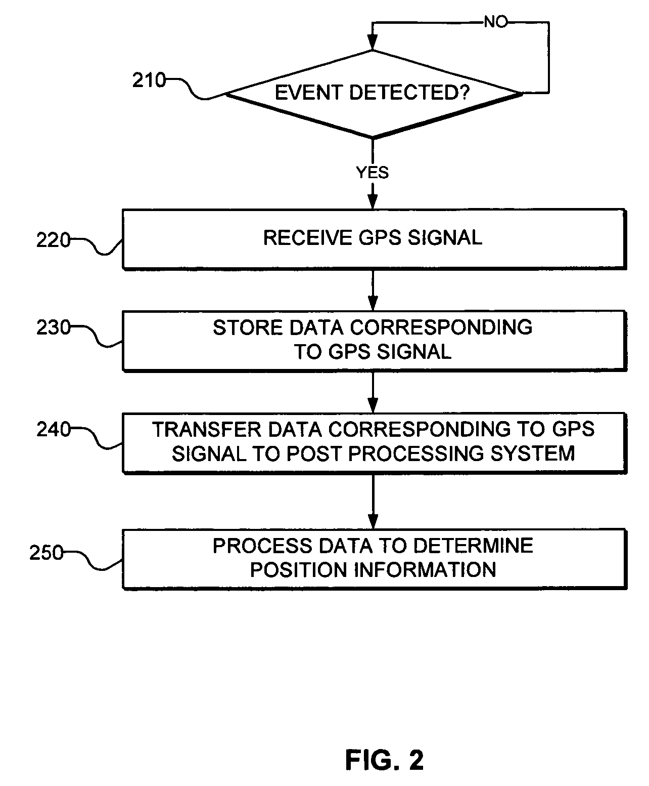
[0023] In accordance with various embodiments, systems and methods are provided for location tagging using post-processing of a satellite positioning signal. FIG. 2 is a flow chart of a positioning signal processing method, in accordance with embodiments of the present invention. In step 210, a system detects the occurrence of a predetermined event. In step 220, the system receives a signal corresponding to the signals detected from a plurality of positioning satellite vehicles, such as GPS satellites. In step 230, the host system stores data corresponding to the received GPS signal. In step 240, the data corresponding to the received GPS signal is transferred to a post-processing system. Finally, in step 250, the data corresponding to the received GPS signal is processed to obtain information regar...


PUM


Abstract

A system is provided for storing positional data received from GPS signals in response to an event, and then processing that positional data at a later time to obtain detailed location information of the system at the time of the event. The received GPS signals may be decimated to a desired sampling rate and then stored for later correlation. In one embodiment, the system is a digital camera having an antenna, an RF front end, and a non-volatile memory device. The event which triggers the storage of the positional data is a photo capture by the digital camera. The positional data, in decimated but uncorrelated form, is stored with the image data in the non-volatile memory device. The positional data can then be transferred with the image data to a separate device, such as a personal computer, for post-processing.

Description

BACKGROUND OF THE INVENTION [0001] Satellite-based positioning systems include constellations of earth orbiting satellites that constantly transmit orbit information and ranging signals to receivers. An example of a satellite-based positioning system is the Global Positioning System (GPS), which includes a constellation of earth orbiting satellites, also referred to as GPS satellites, satellite vehicles, or space vehicles. The GPS satellites circle the earth twice a day in a very precise orbit and transmit signal information to the earth. The satellite signal information is received by GPS receivers which can be in portable or mobile units, or in fixed positions on base stations and / or servers. [0002] The GPS receiver uses the satellite signal information to calculate the receiver's precise location. Generally the GPS receiver compares the time GPS signals or satellite signals were transmitted by a satellite with the time of receipt of that signal at the receiver. This time differen...

Claims


Application Information

Patent Timeline
Patent Type & Authority Applications(United States)
IPC IPC(8): G01S5/14G01S19/04G01S19/10G01S19/44G01S19/46
CPCG01S19/09G01S19/14H04N1/00127H04N1/00323H04N2101/00H04N2201/0084H04N2201/3253H04N2201/3274G01S19/36
Inventor GRONEMEYER, STEVEN A.
Owner SIRF TECHONOLOGY INC
Why Eureka
Try Eureka