Multiple turboshaft engine control method and system for helicopters

a multi-turboshaft engine and control method technology, applied in engine control, turbine/propulsion fuel control, jet propulsion plants, etc., can solve the problems of limited fuel efficiency gain, significant delay in starting up the engine back up,

Active Publication Date: 2013-06-06
PRATT & WHITNEY CANADA CORP
View PDF9 Cites 29 Cited by
  • Summary
  • Abstract
  • Description
  • Claims
  • Application Information

AI Technical Summary

Problems solved by technology

However, once a turboshaft is stopped, there is a significant delay in starting it back up again.
This delay is associated with the required amount of time to get the engine running at a sufficient RPM (and draw in a sufficient amount of air) for engine operation to begin.
Henceforth, for safety purposes, the typical approach was not to shut down the second engine completely, but to keep it idling, which limited the gain in fuel efficiency.

Method used


Image

  • Multiple turboshaft engine control method and system for helicopters
  • Multiple turboshaft engine control method and system for helicopters
  • Multiple turboshaft engine control method and system for helicopters

Examples


Embodiment Construction

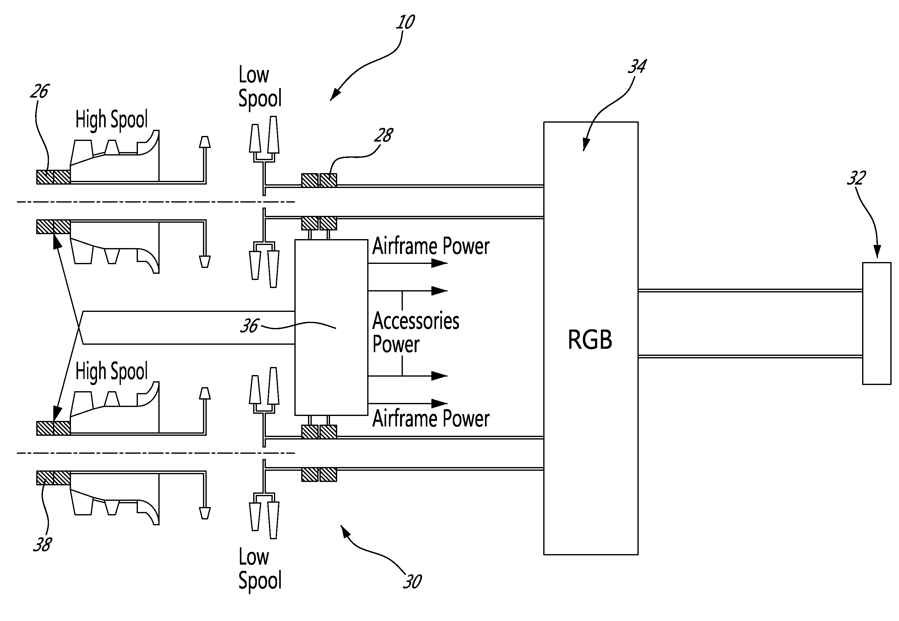
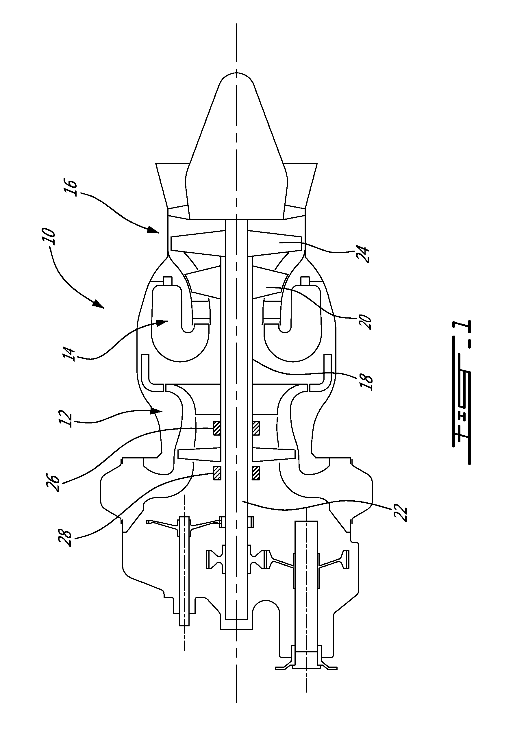
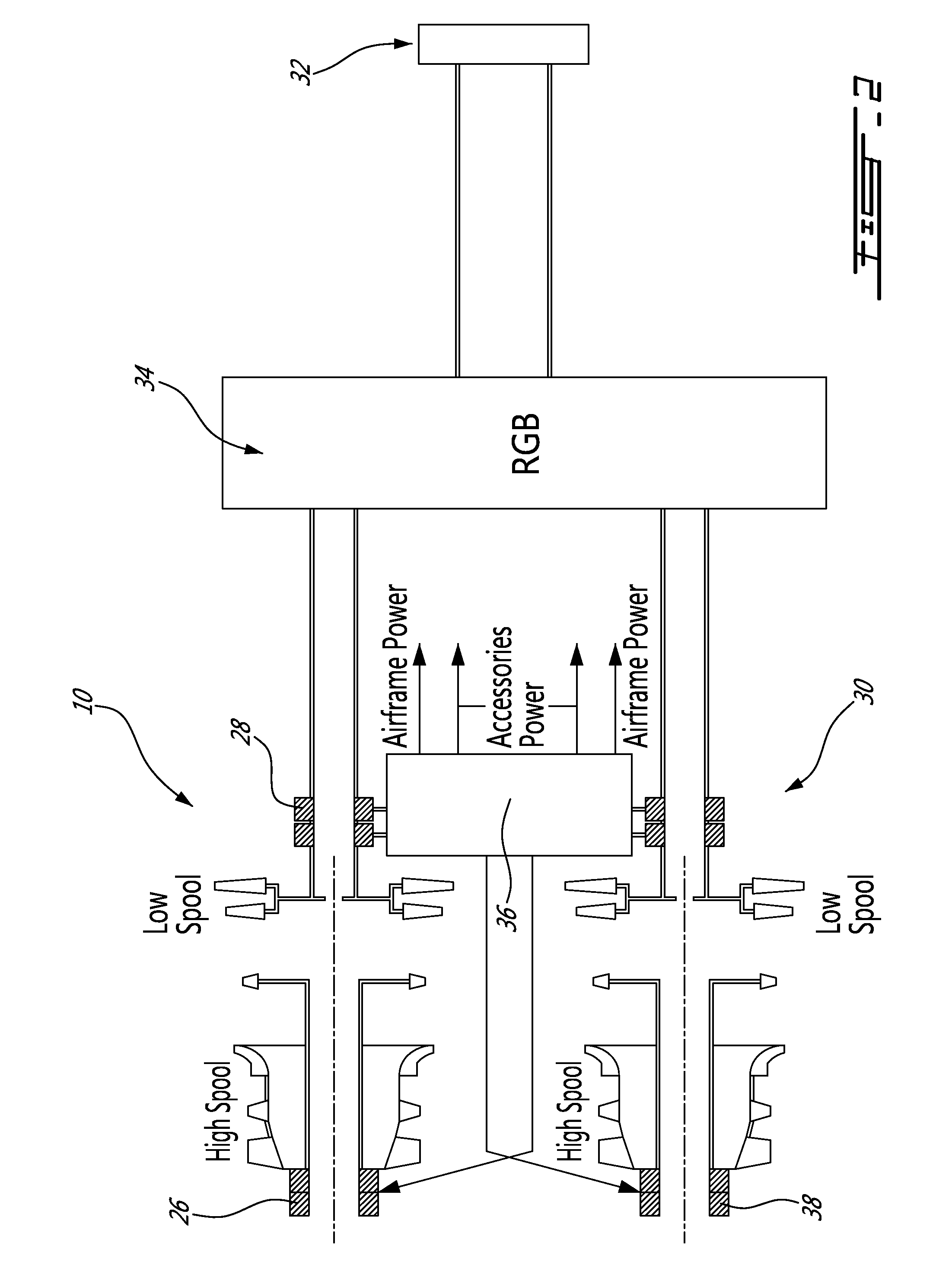
[0012]FIG. 1 illustrates an example of a turbine engine. In this example, the turbine engine 10 is a turboshaft engine generally comprising in serial flow communication, a multistage compressor 12 for pressurizing the air, a combustor 14 in which the compressed air is mixed with fuel and ignited for generating an annular stream of hot combustion gases, and a turbine section 16 for extracting energy from the combustion gases.

[0013]The turbine engine 10 in this example can be seen to include a high pressure spool 18, including a multistage compressor 12 and a high-pressure turbine stage 20, and a low pressure spool 22, including a low-pressure turbine stage 24. The low spool 22 leads to a power shaft via a gear arrangement. The high spool 18 can be refer to herein as a compressor spool, given that it contains at least one compressor stage, and the low spool 22 can be reffered to herein as the power spool.

[0014]In this example, the turbine engine 10 is of the more-electric engine type ...


PUM


Abstract

Electric power from the low spool of a turboshaft engine is transferred to drive the compressor of an other turboshaft engine. This is used to assist in maintaining the other turboshaft idling while a single engine provides flight power or to increase acceleration for instance.

Description

TECHNICAL FIELD[0001]The application relates generally to the management of a multiple turboshaft arrangement in a helicopter, more particularly, involving electrical power transfer between engines.BACKGROUND OF THE ART[0002]Helicopters are often provided with at least two turboshaft engines. Both engines are connected to the main rotor via a common reduction gearbox, and each of the engines is sized to account for the worst-case scenario of the other engine failing at takeoff. Accordingly, the power of each engine is significantly greater than what is required for cruising.[0003]In cruising conditions, operating a single engine at a relatively high regime instead of both at a lower regime can allow significantly better fuel efficiency. However, once a turboshaft is stopped, there is a significant delay in starting it back up again. This delay is associated with the required amount of time to get the engine running at a sufficient RPM (and draw in a sufficient amount of air) for eng...

Claims


Application Information

Patent Timeline
Patent Type & Authority Applications(United States)
IPC IPC(8): F02C6/20F02C9/00
CPCF02C7/36F05D2220/329F02C9/00F01D15/10F01D25/36F02C3/10F02C3/113F02C9/56F02C9/42F02C6/02F05D2270/053
Inventor MORGAN, KEITH
Owner PRATT & WHITNEY CANADA CORP
Why Eureka
Try Eureka