Drive unit of fuel injection device

a fuel injection device and drive unit technology, applied in the direction of liquid fuel feeders, machines/engines, electric control, etc., can solve the problems of increasing the minimum injection quantity, and increasing individual irregularities among manufactured fuel injection devices, so as to reduce the minimum injection quantity and the valve element's behavior to be stable.

Active Publication Date: 2013-06-06
HITACHI ASTEMO LTD
View PDF14 Cites 44 Cited by
  • Summary
  • Abstract
  • Description
  • Claims
  • Application Information

AI Technical Summary

Benefits of technology

[0019]According to the present invention, the current value can be rapidly switched to the hold current value and hence, the unstable behavior of the valve element can be suppressed thus providing a drive unit of a fuel injection device which can reduce a minimum injection quantity.

Problems solved by technology

However, in a region where the injection pulse width is short, the injection quantity is not changed linearly with respect to the injection pulse width due to a rebound phenomenon which occurs when a movable element impinges on a stopper or the like (bound behavior of a movable element) thus giving rise to a drawback that a minimum injection quantity which the fuel injection device can control is increased.
Further, there may be a case where the injection quantity does not become stable due to the above-mentioned rebound phenomenon of the movable element, and there has been a case where this unstable injection quantity causes the increase of the minimum injection quantity or causes the increase of individual irregularities among manufactured fuel injection devices.

Method used


Image

  • Drive unit of fuel injection device
  • Drive unit of fuel injection device
  • Drive unit of fuel injection device

Examples


embodiment 1

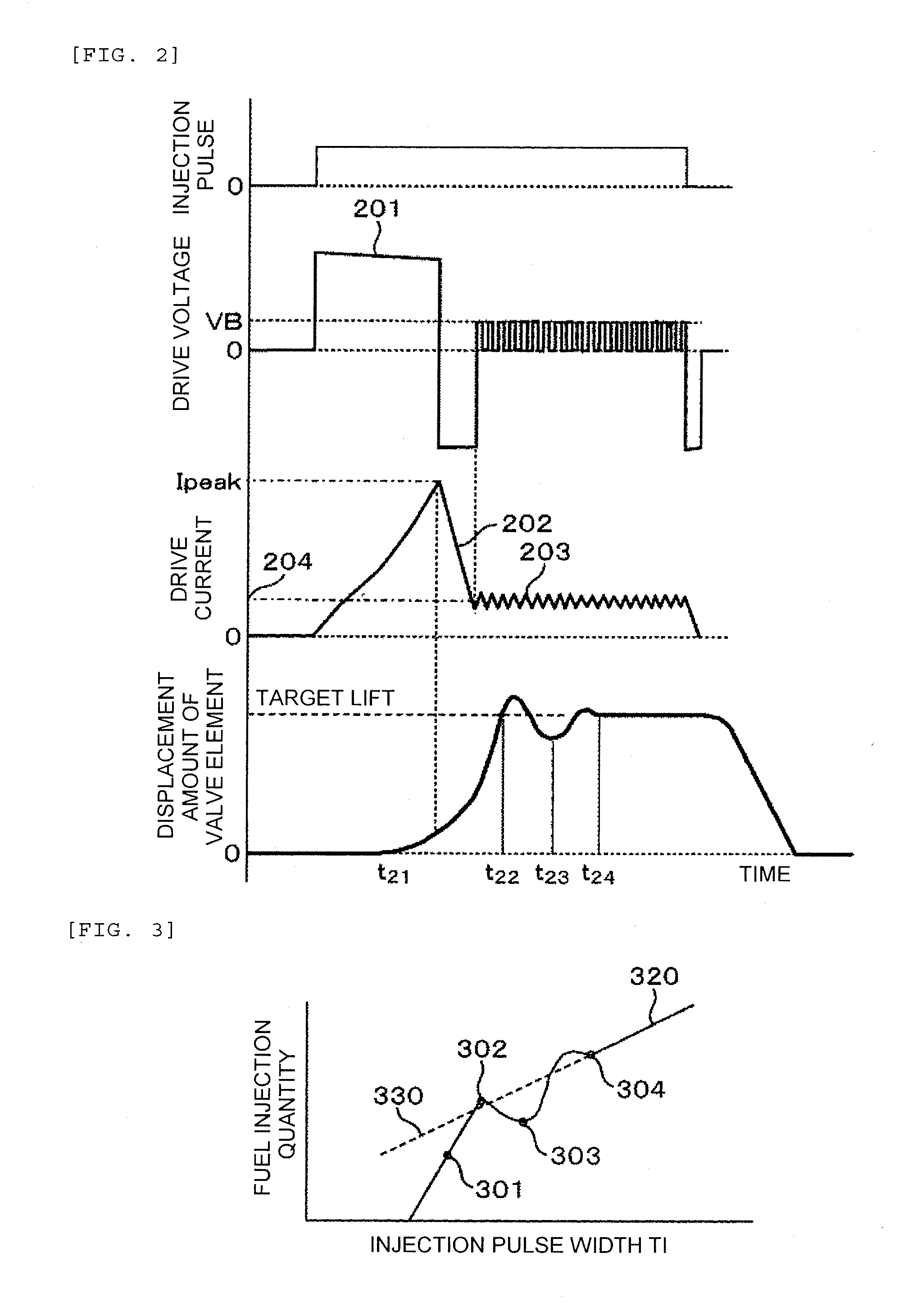
[0057]The first embodiment of the present invention is explained in conjunction with FIG. 4 and FIG. 5. FIG. 4 is a graph showing the relationship among an injection pulse outputted from an ECU (engine control unit), a drive voltage and a drive current (excitation current) which are supplied to a fuel injection device, and a displacement amount of a valve element (behavior of the valve element). FIG. 5 is a graph showing the relationship between a pulse width Ti of the injection pulse outputted from the ECU and a fuel injection quantity.

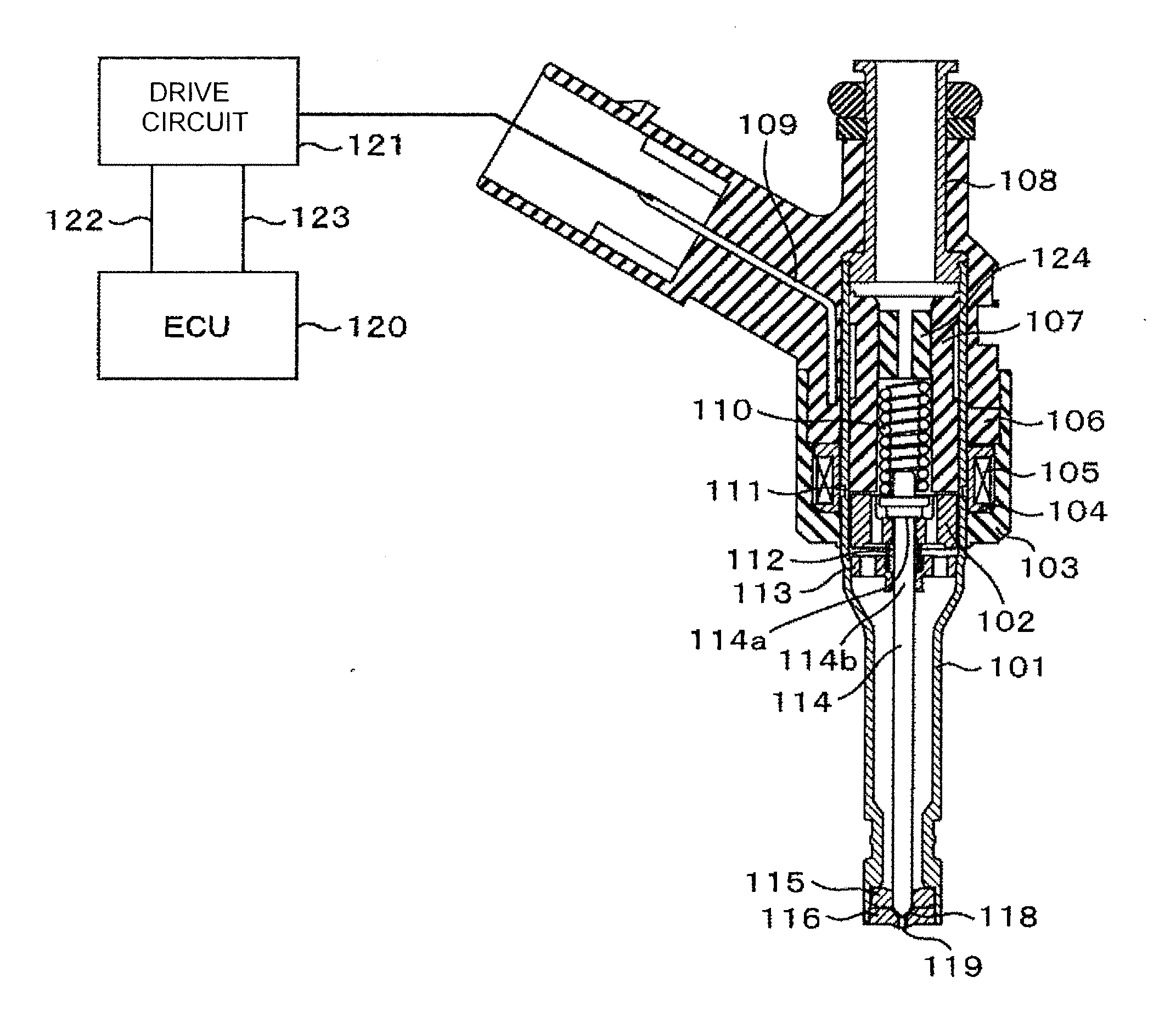
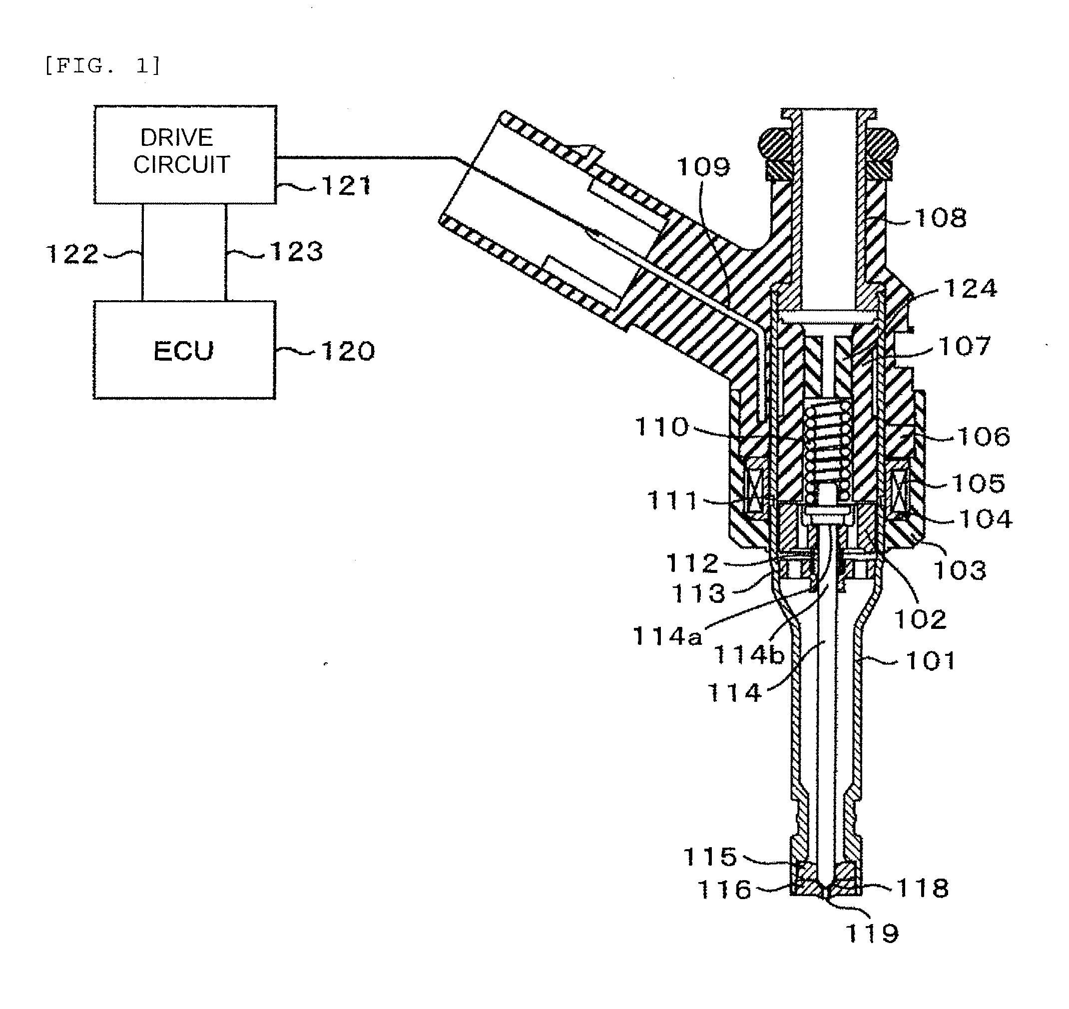
[0058]When an injection pulse is inputted to a drive circuit 121 from an ECU 120, a high voltage 410 is applied to a solenoid 105 from a high voltage source whose voltage is boosted to a voltage higher than a battery voltage so that the supply of an electric current to the solenoid 105 is started. When a current value reaches a preset peak current value Ipeak, the drive circuit 121 stops the applying of the high voltage and sets the voltage to be app...

embodiment 2

[0072]The second embodiment is explained in conjunction with FIG. 6. FIG. 6 is a graph showing the relationship among an injection pulse outputted from an ECU (engine control unit), a drive voltage and a drive current (excitation current) which are supplied to a fuel injection device, and a displacement amount of a valve element (behavior of the valve element). A control of the drive voltage or the drive current explained hereinafter can be carried out using the drive circuit shown in FIG. 8 which is explained in conjunction with the first embodiment by changing a control method (switching timing) of the drive voltage or the drive current.

[0073]When an injection pulse is inputted to the drive circuit, a high voltage 610 is applied to a solenoid 105 from a high voltage source VH whose voltage is boosted to a voltage higher than a battery voltage so that the supply of an electric current to the solenoid 105 is started. When a current value reaches a preset peak current value Ipeak, th...

embodiment 3

[0080]The third embodiment is explained in conjunction with FIG. 7. FIG. 7 is a graph showing the relationship among an injection pulse outputted from an ECU (engine control unit), a drive voltage and a drive current (excitation current) which are supplied to a fuel injection device, and a displacement amount of a valve element (behavior of the valve element). A control of the drive voltage or the drive current explained hereinafter is carried out using the drive circuit shown in FIG. 8 which is explained in conjunction with the first embodiment by changing a control method (switching timing) of the drive voltage or the drive current.

[0081]The point which makes this embodiment differ from the first embodiment lies in that when a current value reaches a preset current value 713, a drive circuit 121 performs a control such that a high voltage source VH is applied by switching so that a predetermined electric current 702 is held for a fixed time. Advantageous effects acquired by holdin...


PUM


Abstract

In a drive unit of a fuel injection device, an electric current is supplied to the fuel injection device by applying a high voltage to the fuel injection device from a high voltage source whose voltage is boosted to a voltage higher than a battery voltage at the time of opening a valve of the fuel injection device. Thereafter, the electric current supplied to the fuel injection device is lowered to a current value at which a valve element cannot be held in a valve open state by stopping the applying of the high voltage from the high voltage source. Thereafter, in a stage where a supply current is switched to a hold current, another high voltage is applied to the fuel injection device from the high voltage source.

Description

TECHNICAL FIELD[0001]The present invention relates to a drive unit of a fuel injection device which is used in an internal combustion engine, for example.BACKGROUND ART[0002]Recently, there has been a demand for the enhancement of fuel economy (fuel consumption ratio) in an internal combustion engine in view of tightening of regulations on the emission of carbonic acid gas or from the fear of the depletion of fossil fuels. To satisfy such a demand, efforts have been made to enhance fuel economy by reducing various losses in the internal combustion engine. In general, the reduction of losses can decrease an output necessary for an operation of the internal combustion engine and hence, a minimum output of the internal combustion engine can be made small. In such an internal combustion engine, it is necessary to supply fuel by controlling a fuel quantity such that even a small fuel quantity corresponding to the minimum output can be controlled.[0003]Further, recently, a downsizing engi...

Claims


Application Information

Patent Timeline
Patent Type & Authority Applications(United States)
IPC IPC(8): F02M69/04
CPCF02D41/20F02D2041/2013F02M69/04F02M51/061F02D2041/2037F02D41/3005F02D2041/2003F02D2041/2051
Inventor KUSAKABE, RYOABE, MOTOYUKIEHARA, HIDEHARUISHIKAWA, TOHRUMAYUZUMI, TAKUYAHIRAKU, KENJI
Owner HITACHI ASTEMO LTD
Why Eureka
Try Eureka