Thermoelectric devices

a technology of thermoelectric devices and junction materials, applied in the direction of thermoelectric device junction materials, material nanotechnology, electrical devices, etc., can solve the problem of hard to increase a value of zt, and achieve the effect of improving the thermoelectric efficiency

Active Publication Date: 2013-06-06
ELECTRONICS & TELECOMM RES INST
View PDF6 Cites 4 Cited by
  • Summary
  • Abstract
  • Description
  • Claims
  • Application Information

AI Technical Summary

Benefits of technology

[0006]Embodiments of the inventive concepts provide thermoelectric devices with improved thermoelectric efficiency.

Problems solved by technology

Since the use of fossil fuels causes various environmental problems, such as atmospheric pollution, global warming, or an increasing amount of carbon dioxide in the atmosphere, there is a need to replace the fossil fuels with alternative clean energy.
In most cases, electric conductivity and thermal conductivity of a material have a proportional relationship to each other, and thus, it is hard to increase a value of ZT.

Method used


Image

  • Thermoelectric devices
  • Thermoelectric devices
  • Thermoelectric devices

Examples


Embodiment Construction

[0037]Example embodiments of the inventive concepts will now be described more fully with reference to the accompanying drawings, in which example embodiments are shown. Example embodiments of the inventive concepts may, however, be embodied in many different forms and should not be construed as being limited to the embodiments set forth herein; rather, these embodiments are provided so that this disclosure will be thorough and complete, and will fully convey the concept of example embodiments to those of ordinary skill in the art. In the drawings, the thicknesses of layers and regions are exaggerated for clarity. Like reference numerals in the drawings denote like elements, and thus their description will be omitted.

[0038]It will be understood that when an element is referred to as being “connected” or “coupled” to another element, it can be directly connected or coupled to the other element or intervening elements may be present. In contrast, when an element is referred to as bein...


PUM


Abstract

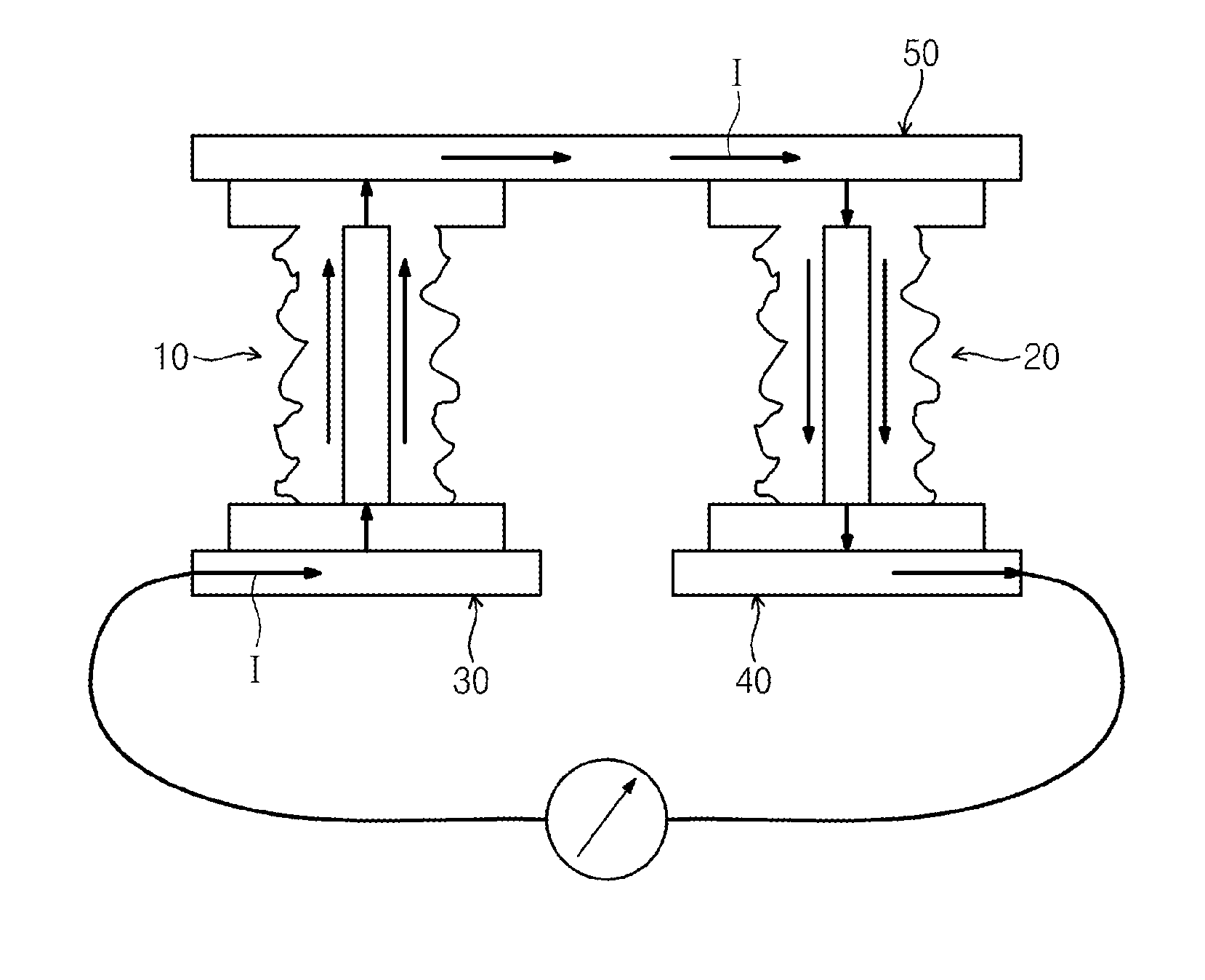
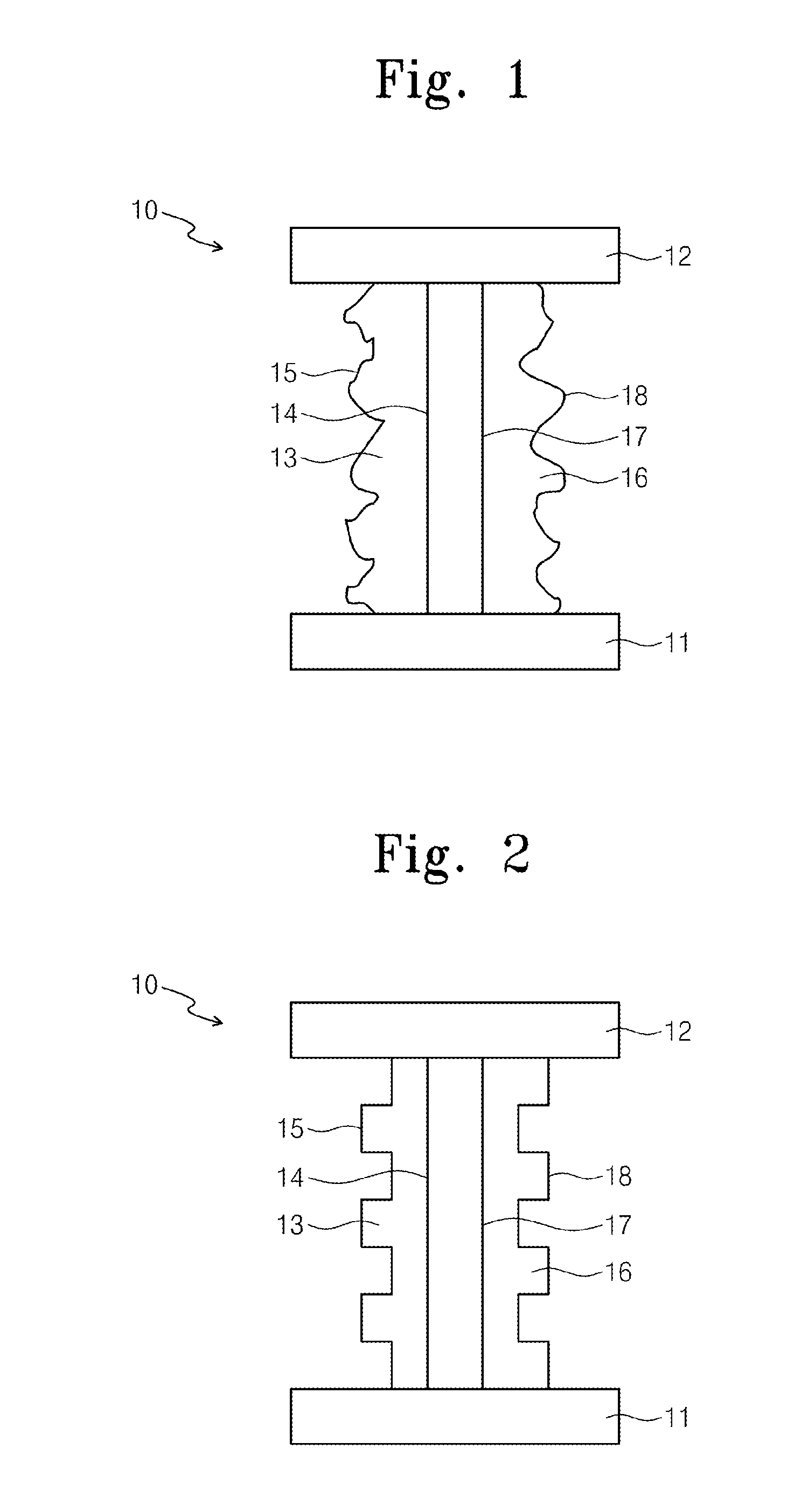
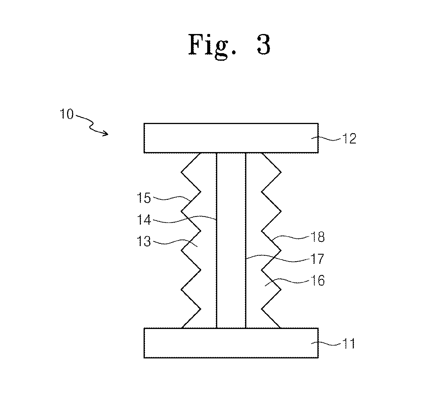
Provided is a thermoelectric device including two legs having a rough side surface and a smooth side surface facing each other. Phonons may be scattered by the rough side surface, thereby decreasing thermal conductivity of the device. Flowing paths for electrons and phonons may become different form each other, because of a magnetic field induced by an electric current passing through the legs. The smooth side surface may be used for the flowing path of electrons. As a result, in the thermoelectric device, thermal conductivity can be reduced and electric conductivity can be maintained.

Description

CROSS-REFERENCE TO RELATED APPLICATIONS[0001]This U.S. non-provisional patent application claims priority under 35 U.S.C. §119 to Korean Patent Application No. 10-2011-0128273, filed on Dec. 2, 2011, in the Korean Intellectual Property Office, the entire contents of which are hereby incorporated by reference.BACKGROUND OF THE INVENTION[0002]Embodiments of the inventive concepts relate to a thermoelectric device, and in particular, to a thermoelectric device including a pair of legs with rugged portions.[0003]Since the use of fossil fuels causes various environmental problems, such as atmospheric pollution, global warming, or an increasing amount of carbon dioxide in the atmosphere, there is a need to replace the fossil fuels with alternative clean energy. One of clean energy sources is a thermoelectric device converting thermal energy into electrical energy. A heat source of the thermoelectric device may be radiant heat (e.g., solar heat), terrestrial heat, body heat, waste heat, an...

Claims


Application Information

Patent Timeline
Patent Type & Authority Applications(United States)
IPC IPC(8): H01L35/32H01L35/14H01L35/16B82Y99/00
CPCB82Y30/00H01L35/32H10N10/17H10N10/80
Inventor HYUN, YOUNGHOONJANG, MOON GYUPARK, YOUNG SAMZYUNG, TAEHYOUNGYANG, YIL SUKKWON, JONG-KEE
Owner ELECTRONICS & TELECOMM RES INST
Why Eureka
Try Eureka