Handheld electronic device

Inactive Publication Date: 2013-06-06
HTC CORP
View PDF8 Cites 2 Cited by
  • Summary
  • Abstract
  • Description
  • Claims
  • Application Information

AI Technical Summary

Benefits of technology

[0006]The invention provides a handheld electronic device, wherein a light emitting region of a backlight module exten

Problems solved by technology

However, the light emitting diodes that provide light for the keys increase the production cost of the handheld electronic device.
In addit

Method used


Image

  • Handheld electronic device
  • Handheld electronic device
  • Handheld electronic device

Examples


Embodiment Construction

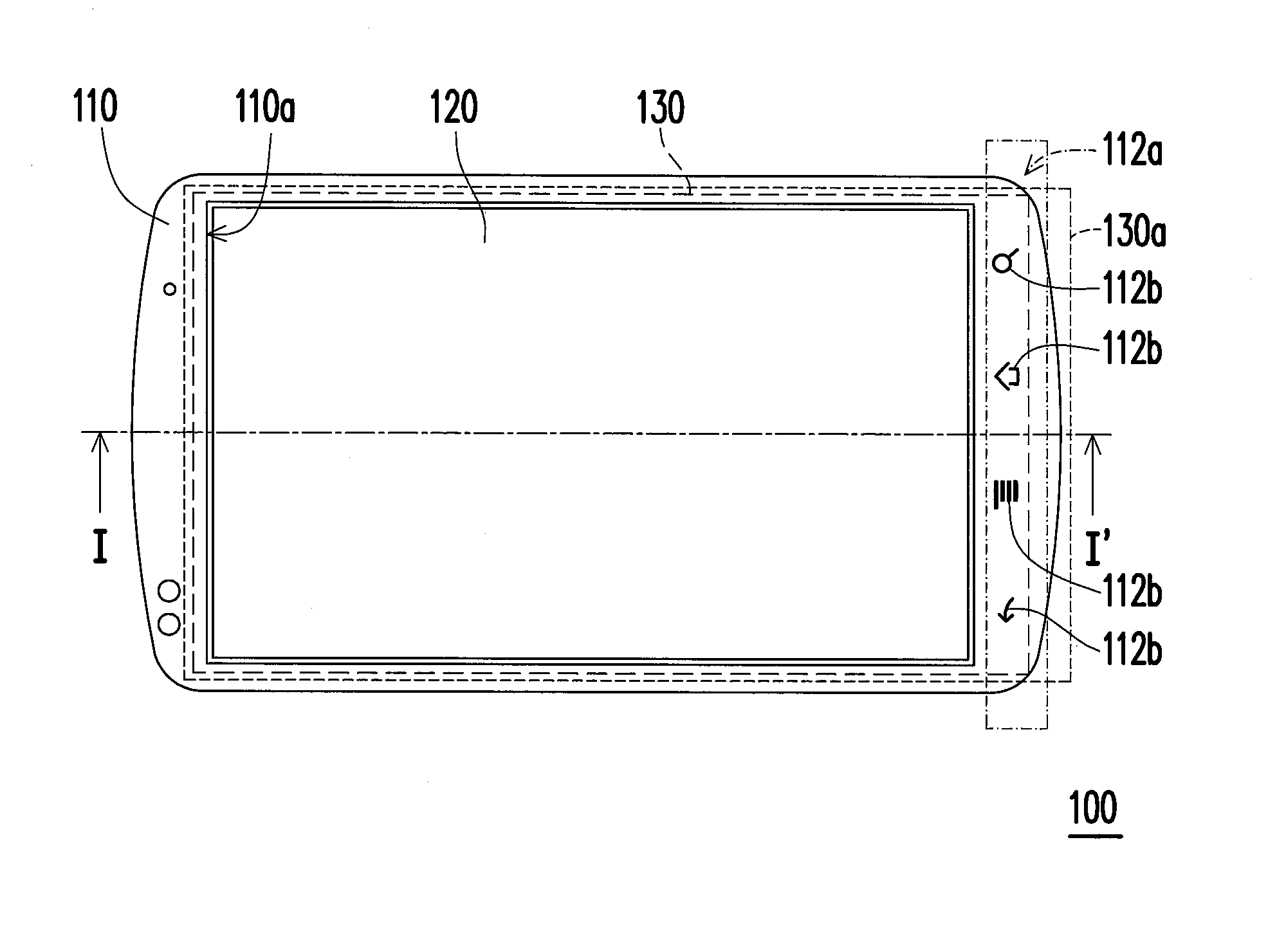
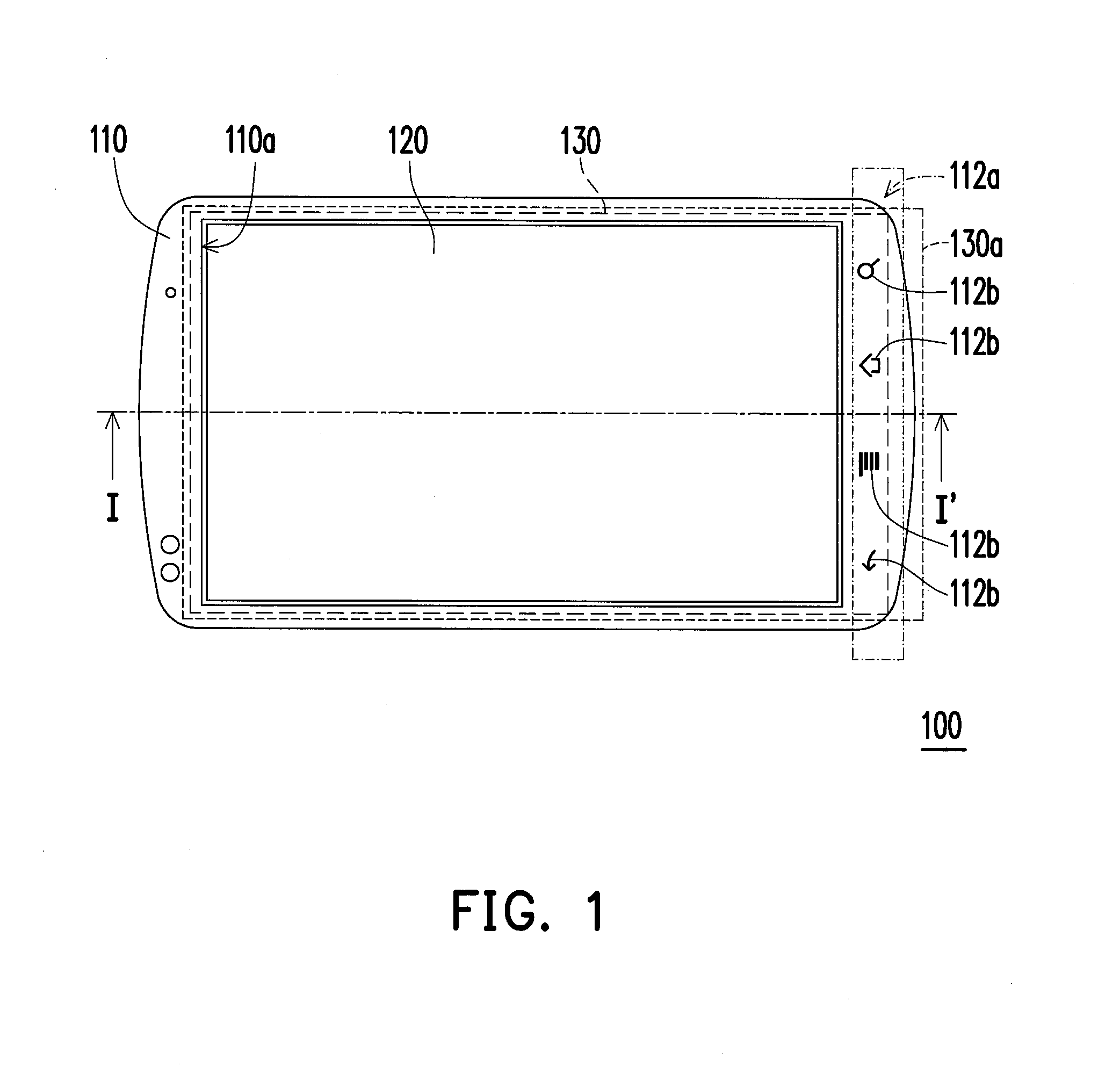
[0014]FIG. 1 is a schematic view illustrating a handheld electronic device according to an embodiment of the invention. FIG. 2 is a schematic view of a display panel and a backlight module of FIG. 1. Referring to FIG. 1 and FIG. 2, in the embodiment, the handheld electronic device 100 includes a housing 110, a display panel 120, and a backlight module 130. The housing 110 includes a display opening 110a and a transparent region 112a located outside of the display opening 110a. The display panel 120 is disposed in the display opening 110a. The backlight module 130 is disposed in the housing 110. The backlight module 130 has a light emitting region 130a located below the display panel 120, and is adapted to provide a plane light source to the display panel 120. The light emitting region 130a further extends outside of the display panel 120 so that a part of the plane light source is sent out the housing 110 through the transparent region 112a. Since the light emitting region 130a of t...


PUM


Abstract

A handheld electronic device including a housing, a display panel and a backlight module is provided. The housing has a display opening and a transparent region located outside of the display opening. The display panel is disposed in the display opening. The backlight module is disposed in the housing. The backlight module has a light emitting region which is located under the display panel, adapted to provide a plane light source to the display panel. The light emitting region further extends to outside of the display panel so that a part of the plane light source is sent out the housing through the transparent region.

Description

BACKGROUND OF THE INVENTION[0001]1. Field of the Invention[0002]The invention relates to a handheld electronic device. More particularly, the invention relates to a handheld electronic device that uses a backlight module to provide display light.[0003]2. Description of Related Art[0004]A handheld electronic device is an electronic device which a user can carry around and operate on. The handheld electronic device is usually small and light for the user to carry conveniently. Common handheld electronic devices are, for example, a mobile phone, a multimedia player, a personal digital assistant (PDA), a handheld game console, a handheld global positioning system, or a notebook.[0005]Using a mobile phone as an example, a plurality of keys are usually disposed in an area other than the display area of the display panel. Light emitting diodes are disposed below the keys, so as to provide light for the keys to be used. However, the light emitting diodes that provide light for the keys incr...

Claims


Application Information

Patent Timeline
IPC IPC(8): G06F3/041H05K7/00
CPCG02F1/133615G02B6/006G02F2001/133626G02F1/133626
Inventor CHENG, YUAN-SHENGTSAI, JUNG-YUANCHIANG, WEI-HUANG
Owner HTC CORP
Why Eureka
Try Eureka