System for Protecting Light Optical Components during Laser Ablation

a technology for protecting light optical components and laser ablation, which is applied in the direction of laser beam welding apparatus, manufacturing tools, welding/soldering/cutting articles, etc., can solve the problems of high-precision milling or sample removal often requiring tradeoffs, ion beam damage to sample surfaces, and limited processing rate of lmis fib

Active Publication Date: 2014-10-02
FEI CO
View PDF5 Cites 8 Cited by
  • Summary
  • Abstract
  • Description
  • Claims
  • Application Information

AI Technical Summary

Benefits of technology

[0012]An object of the invention is to provide a method and apparatus for performing laser ablation within a vacuum chamber in a charged particle beam system while simultaneously protecting the light optical components of the apparatus utilized to focus the laser from being coated with debris resulting from the ablation process. According to preferred embodiments of the present invention, a protective transparent screen is used to shield the laser optical components. A preferred screen could be replaced or repositioned without breaking vacuum in the sample chamber and would not be particularly susceptible to undesirable charging effects.

Problems solved by technology

Because electrons are much lighter than ions, electron beams are typically limited to removing material by inducing a chemical reaction between an etchant vapor and the substrate.
Because ion beams tend to damage sample surfaces even when used to image, ion beam columns are often combined with electron beam columns in dual beam systems.
Unfortunately, high-precision milling or sample removal often requires some tradeoffs.
The processing rate of the LMIS FIB is limited by the current in the beam.
As the current is increased, it is harder to focus the beam into a small spot.
Lower beam currents allow higher resolution, but result in lower milling rates and hence longer processing times in production applications and in laboratories.
Further, even at higher beam currents, focused ion beam milling may still be unacceptably slow for some micromachining applications.
Thus, while a charged particle beam typically has greater resolution than a laser beam and can micromachine extremely small structures, the beam current is limited and the micromachining operation can be unacceptably slow.
Laser micromachining, on the other hand, is generally much faster, but has poorer resolution due to diffraction.
Unfortunately, laser ablation, because of the large volume of debris produced, can tend to result in the gradual coating of the laser objective lens with debris, which ultimately degrades the performance of the laser.
Neither of these techniques can be easily used in a combined charged particle beam / laser system, however.
The use of a gas is not practical because the sample chamber must be under vacuum for charged particle beam operation.
Also, the use of glass covers is impractical; both because it requires venting the sample chamber to atmosphere to replace the covers and also because glass suffers from a very undesirable charging effect that will degrade the operation of the charged particle beam, especially for imaging purposes.

Method used


Image

  • System for Protecting Light Optical Components during Laser Ablation
  • System for Protecting Light Optical Components during Laser Ablation
  • System for Protecting Light Optical Components during Laser Ablation

Examples


Embodiment Construction

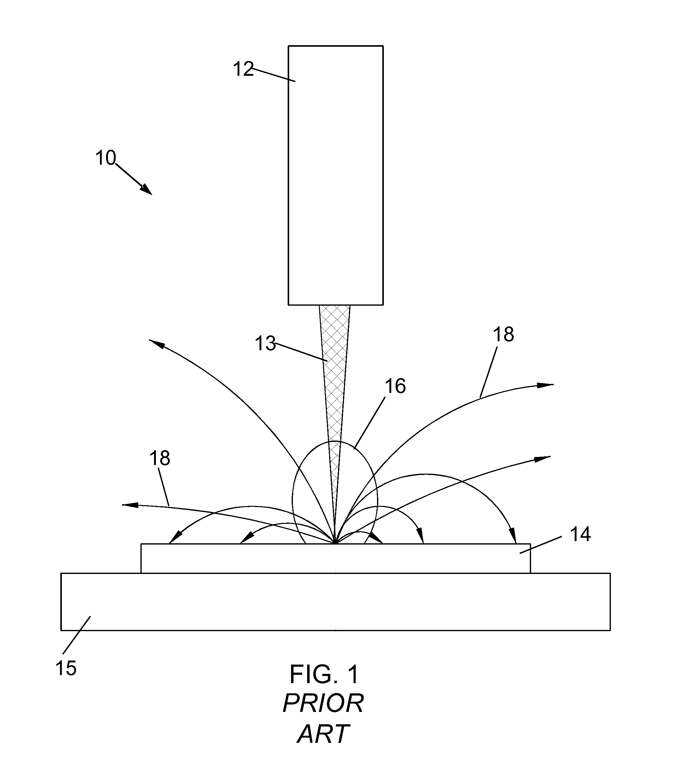
[0026]Applicants have discovered that the use of laser ablation within a vacuum chamber involves difficulties with debris buildup on the laser optics that are not seen in atmospheric laser ablation. Not only are the common methods for mitigating debris buildup not practical for ablation formed inside a vacuum chamber, as discussed above, but the problem is actually greater for ablation performed in a vacuum because debris will actually travel farther since it is not slowed by collisions with gas molecules in the atmosphere.

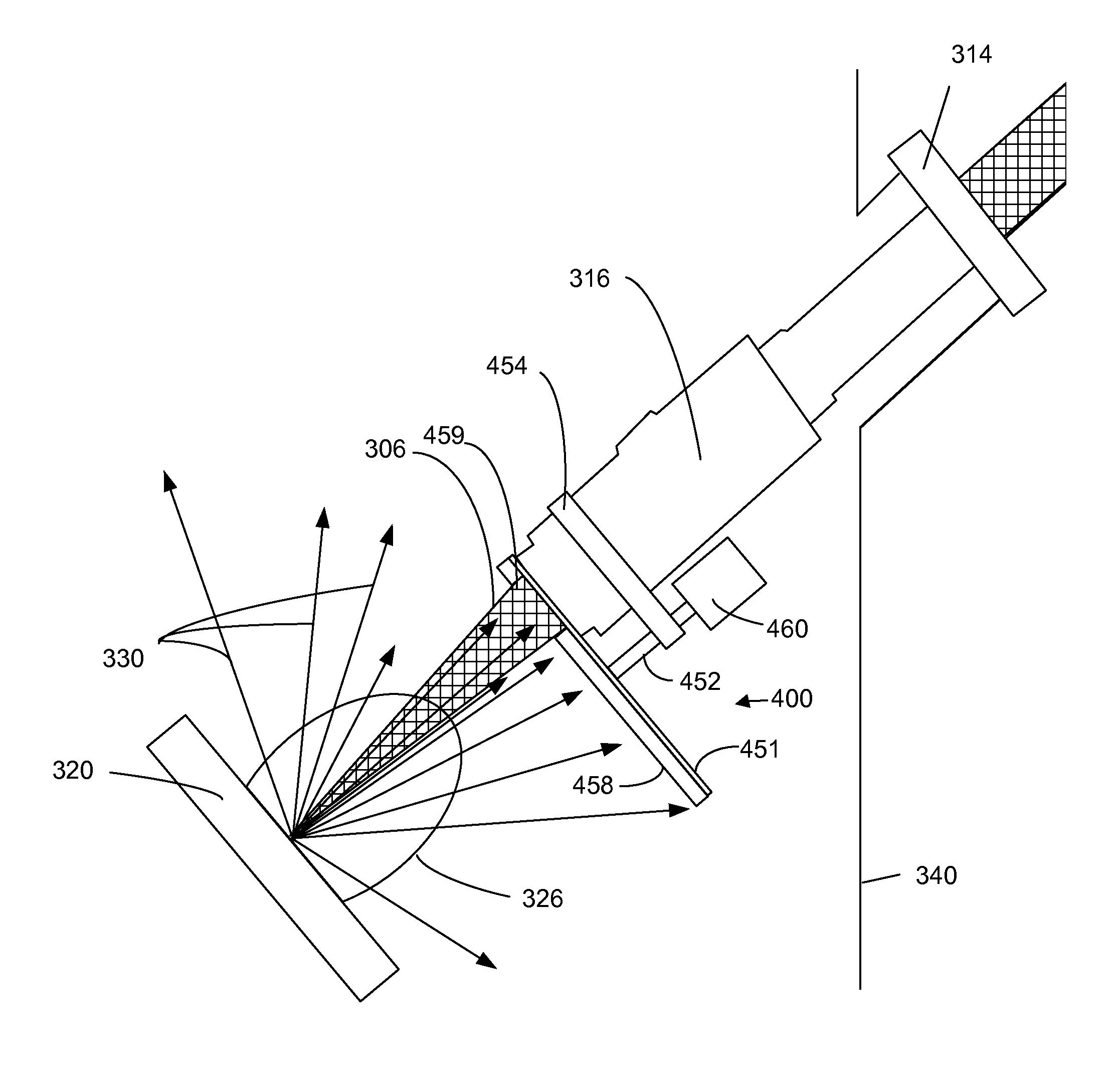
[0027]Preferred embodiments of the present invention thus provide a protective transparent screen that can be used to shield the laser optical components during laser ablation. Preferred embodiments should be easily replaced or repositionable without breaking vacuum in the sample chamber.

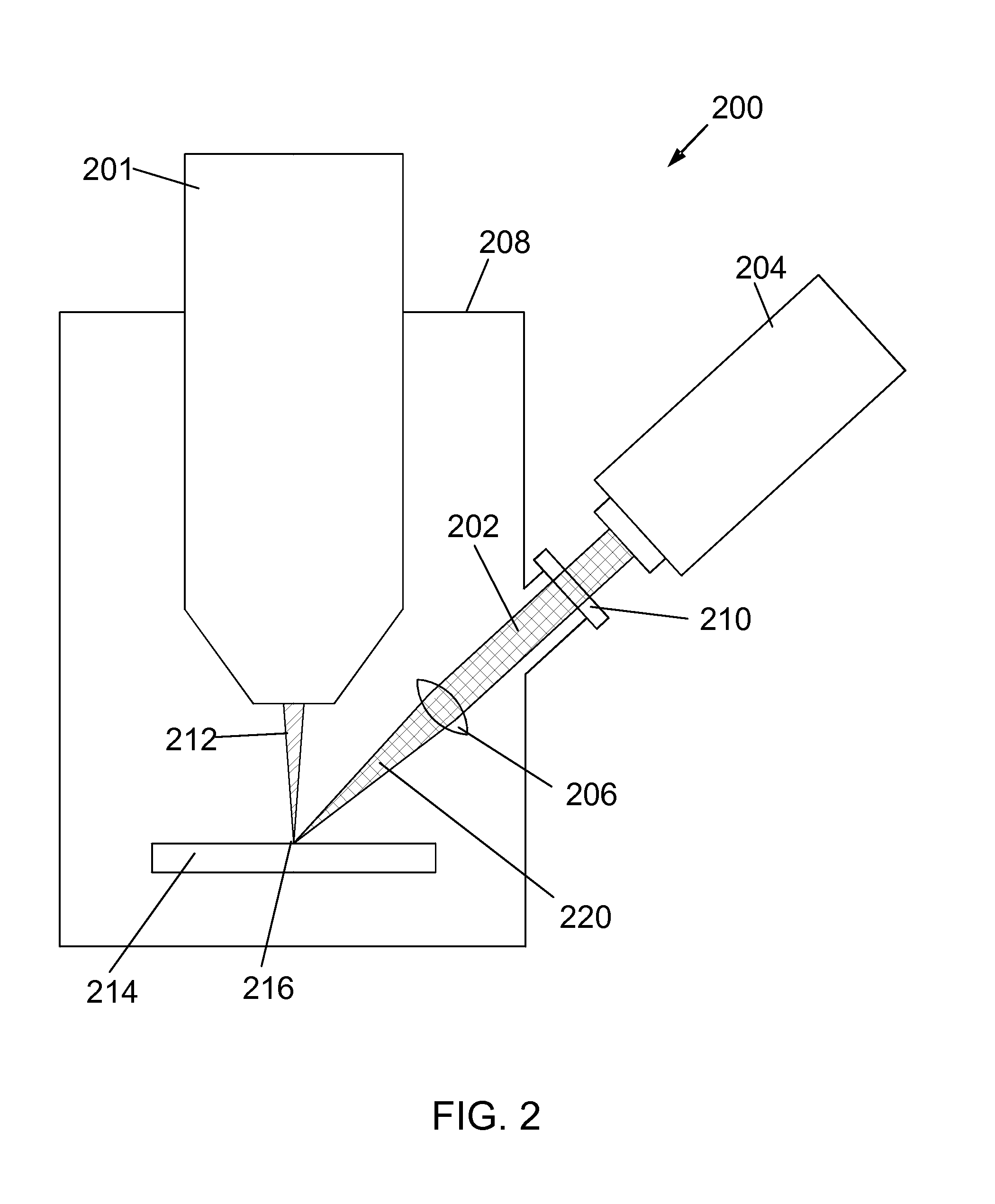
[0028]FIG. 2 shows a dual beam system having a combination charged particle beam column 201 and laser 204. Such a dual beam system is described in U.S. Pat. App. No. 2011 / 0248164 ...


PUM

PropertyMeasurementUnit
energyaaaaaaaaaa
transparentaaaaaaaaaa
transparent conductiveaaaaaaaaaa

Abstract

A method and apparatus to perform laser ablation in the vicinity of a charged particle beam while simultaneously protecting the light optical components of the apparatus utilized to perform the ablation from being coated with debris resulting from the ablation process. According to preferred embodiments of the present invention, a protective transparent screen is used to shield the laser optical components. A preferred screen could be replaced or repositioned without breaking vacuum in the sample chamber and would not be particularly susceptible to undesirable charging effects.

Description

[0001]This Application claims priority from U.S. Provisional Application No. 61 / 618,772, filed Mar. 31, 2012, which is hereby incorporated by reference.TECHNICAL FIELD OF THE INVENTION[0002]The present invention relates to protection of light optical components when laser ablation is performed in the vicinity of a charged particle beam.BACKGROUND OF THE INVENTION[0003]Charged particle beam systems are used in a variety of applications, including the manufacturing, repair, and inspection of miniature devices, such as integrated circuits, magnetic recording heads, and photolithography masks. Charged particle beams include ion beams and electron beams.[0004]Ions in a focused beam typically have sufficient momentum to micromachine by physically ejecting material from a surface. Because electrons are much lighter than ions, electron beams are typically limited to removing material by inducing a chemical reaction between an etchant vapor and the substrate. Both ion beams and electron beam...

Claims


Application Information

Patent Timeline
Patent Type & Authority Applications(United States)
IPC IPC(8): B23K26/06B23K26/36
CPCB23K26/0648B23K26/365B23K15/08B23K26/0635B23K26/122H01J37/3056B23K26/427H01J37/226H01J37/244H01J37/28B23K26/127B23K26/0624B23K26/1224B23K26/361B23K26/706B23K2103/50B23K26/00B23K26/06B23K26/12B23K26/16B23K26/36B23K26/362B23K26/402B23K28/02B23K26/346B23K26/364
Inventor STRAW, MARCUS
Owner FEI CO
Why Eureka
Try Eureka