Optical disc device

a technology of optical discs and optical discs, applied in the direction of optical recording heads, data recording, instruments, etc., can solve the problems of difficult accurate signal reading or writing, difficult reading of a reproduction signal from the focus control plane, and difficult accurate signal writing

Active Publication Date: 2006-01-19
PANASONIC CORP
View PDF4 Cites 10 Cited by
  • Summary
  • Abstract
  • Description
  • Claims
  • Application Information

AI Technical Summary

Benefits of technology

[0035] With the configurations of the present invention, it is possible to cancel stray light components from a proximity plane(s) in an optical disk that has a plurality of signal planes arranged in proximity to each other. Therefore, regardless of the recording state of the proximity plane(s) or the presence of an address pit, accurate reading of a reproduction signal from a focus control plane becomes possible. Moreover, it is possible to detect the amount of stray light from the proximity plane(s). Thus, when signals are recorded on the second signal plane, it is possible to control an intensity of a light spot for recoding signals on the second signal plane so as to allow accurate signal writing on the second signal plane by estimating an amount of light passing through the first signal plane and controlling an output from the light source based on this estimate value. Furthermore, it is also possible to cancel stray light components from a proximity plane(s) in the detection of a focus signal. Thus, focus control that is not affected by the proximity plane(s) becomes possible.

Problems solved by technology

As a result, accurate signal reading or writing cannot be performed.
The amount of stray light varies depending on the recording state of the proximity plane or the presence of an address pit, which makes accurate reading of a reproduction signal from the focus control plane difficult.
Moreover, in the case where signals are recorded on the second signal plane 6b, an amount of light passing through the first signal plane 6a varies depending on the recording state of the first signal plane 6a or the presence of an address pit, which causes the intensity of a light spot for recoding singles on the second signal plane 6b to vary, thereby making accurate signal writing difficult.

Method used


Image

  • Optical disc device
  • Optical disc device
  • Optical disc device

Examples


first embodiment

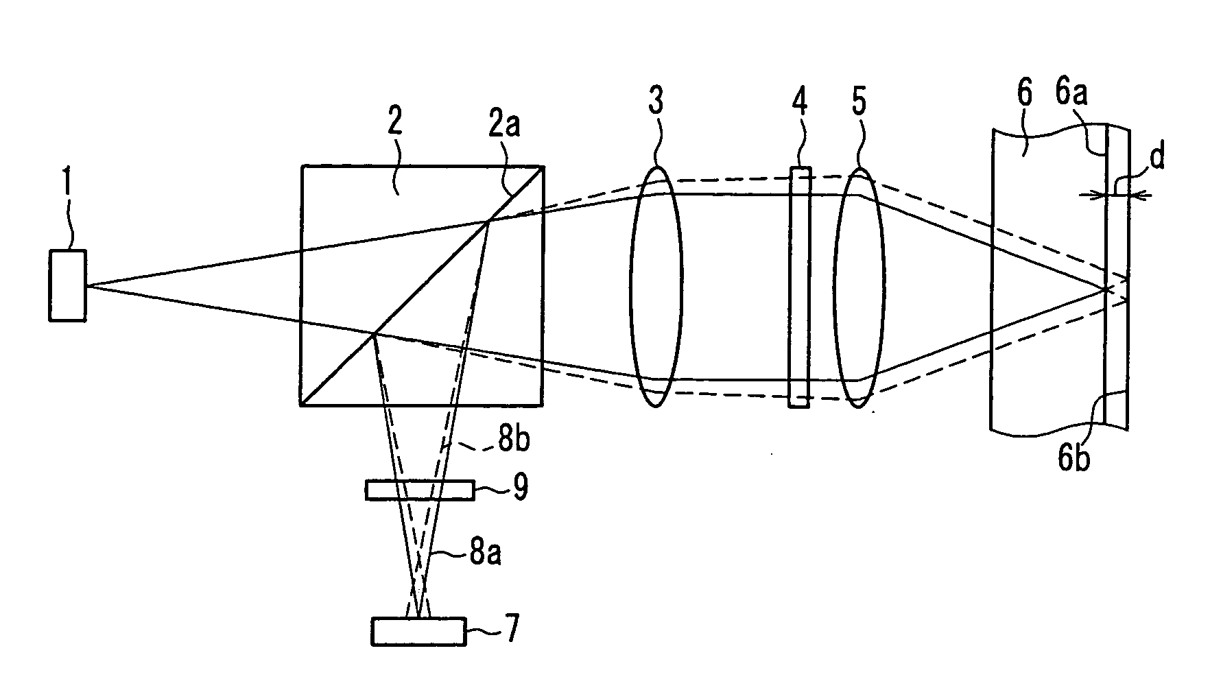
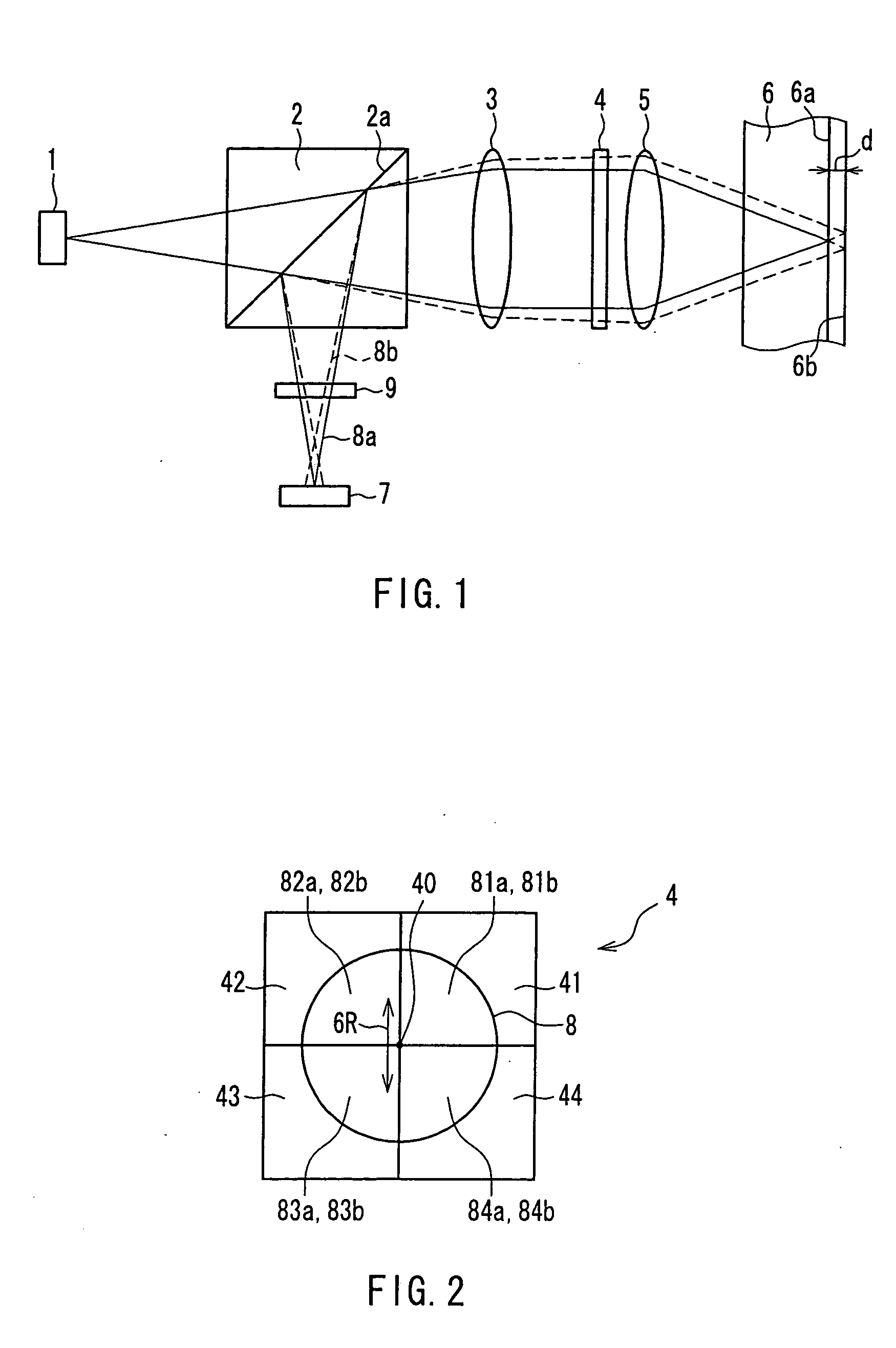
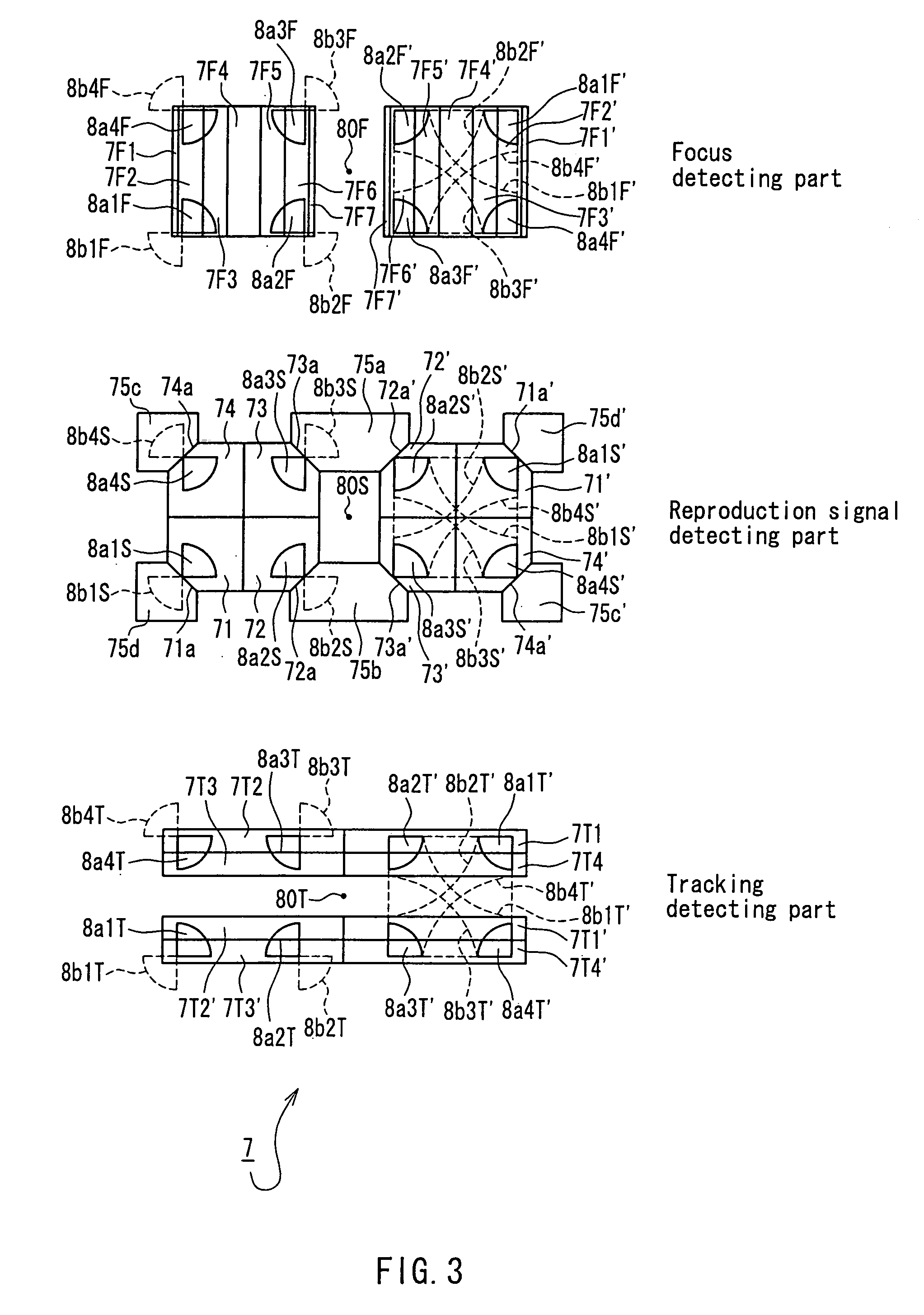
[0068]FIG. 1 is a schematic cross-sectional view showing an optical disk device according to a first embodiment of the present invention (in the state where a focal point of an objective lens is on a first signal plane of an optical disk). FIG. 2 shows a hologram pattern formed on a hologram that serves as an optical splitter in the optical disk device. FIG. 3 shows a photodetection pattern formed on a photodetector that is used in the optical disk device and light distribution on the photodetector in the state shown in FIG. 1. FIG. 4 illustrates positions of focal points of returned lights (0th-order diffracted light beams resulting from the diffraction by a diffraction grating) located on the front side and the back side of the photodetector in the cross-section taken along an optical axis of the optical disk device in the state shown in FIG. 1. The elements common to the optical disk device of the present embodiment and the conventional optical disk device are indicated with the ...

second embodiment

[0103] Although the wavefront is divided into four equal parts by the hologram in the above-described first embodiment, the wavefront may be divided into n equal parts (n is an integer of 2 or more). The following description is directed to an example where the wavefront is divided into two equal parts.

[0104]FIG. 9 shows a hologram pattern formed on a hologram that serves as an optical splitter in an optical disk device according to a second embodiment of the present invention and FIG. 10 shows a photodetection pattern formed on a photodetector that is used in the optical disk device and light distribution on the photodetector. The optical disk device of the present embodiment is the same as the optical disk device of the above-described first embodiment except for a configuration of the hologram and a detection pattern on the photodetector. The elements common to the optical disk device of the present embodiment and the optical disk device of the first embodiment are indicated wit...

third embodiment

[0112]FIG. 11 is a schematic cross-sectional view of an optical disk device according to a third embodiment of the present invention (in the case where light is focused on a first signal plane of an optical disk). FIG. 12 shows a photodetection pattern formed on a photodetector that is used in this optical disk device and light distribution on the photodetector in the state shown in FIG. 11, FIG. 13 is a schematic cross-sectional view showing the optical disk device according to the third embodiment of the present invention (in the case where light is focused on a second signal plane of the optical disk), and FIG. 14 shows a photodetection pattern formed on the photodetector that is used in this optical disk device and light distribution on the photodetector in the state shown in FIG. 13. The optical disk device of the present embodiment is the same as the optical disk device of the above-described first embodiment except that the diffraction grating 9 is not provided and a photodet...


PUM

PropertyMeasurementUnit
sizeaaaaaaaaaa
widthaaaaaaaaaa
angleaaaaaaaaaa

Abstract

An optical disk device is provided that can realize favorable recording/reproduction of signals on/from an optical disk having a plurality of signal planes arranged in proximity to each other. In this optical disk device, a hologram (4) is divided into n(n≧2) regions Ak(k=1, 2, . . . , n) by a straight line that intersects with an optical axis, and a photodetector (7) is divided into at least two regions A and A′. Light emitted from a light source (1) is focused on a signal plane (6a) or (6b) included in a plurality of signal planes of the optical disk by an objective lens (5). Light reflected from a first signal plane (6a) and light reflected from a second signal plane (6b) pass through the objective lens (5) to turn into light beams a and a′, respectively, that enter the hologram (4). 1st-order diffracted light beams ak and ak′ having a common diffraction optical axis are derived from the light beams a and a′ that have entered the regions Ak of the hologram (4), respectively, and are projected on the photodetector (7). Distributions of the 1st-order diffracted light beams ak and ak′ on the photodetector (7) are approximately inverted with respect to an intersection point of the diffraction optical axis and a detection plane. The 1st-order diffracted light beam ak is approximately within the region A and the 1st-order diffracted light beam ak′ is approximately within the region A′.

Description

TECHNICAL FIELD [0001] The present invention relates to an optical disk device used for recording signals on an optical disk or reproduction signals recorded on an optical disk. BACKGROUND ART [0002] Conventionally, as such an optical disk device, the one disclosed in JP2000-133929A has been known, for example. Based on this precedent with a part thereof being modified, the following description is made with reference to FIGS. 26 to 30. [0003]FIG. 26 is a schematic cross-sectional view showing a conventional optical disk device (in the case where a focal point of an objective lens is on a first signal plane of an optical disk). FIG. 27 shows a hologram pattern formed on a hologram that is used in the optical disk device. FIG. 28 shows a photodetection pattern formed on a photodetector that is used in the optical disk device and light distribution on the photodetector in the state shown in FIG. 26. FIG. 29 is a schematic cross-sectional view showing the conventional optical disk devi...

Claims


Application Information

Patent Timeline
Patent Type & Authority Applications(United States)
IPC IPC(8): G11B7/00G11B7/13G11B7/131G11B7/133G11B7/135G11B7/1353
CPCG11B7/0943G11B7/131G11B2007/0013G11B7/1353G11B7/133
Inventor NISHIWAKI, SEIJIMOMOO, KAZUOSAITOH, YOUICHI
Owner PANASONIC CORP
Why Eureka
Try Eureka