Medium transportation device and recording apparatus

a technology of transportation device and recording device, which is applied in the direction of thin material processing, article separation, printing, etc., can solve the problems of reducing the detection accuracy of the transportation distance of the medium, affecting and displaced speckle patterns generated in the light reflected from the medium, so as to achieve the effect of facilitating lifting and improving the detection accuracy of the detector

Active Publication Date: 2013-06-06
SEIKO EPSON CORP
View PDF2 Cites 42 Cited by
  • Summary
  • Abstract
  • Description
  • Claims
  • Application Information

AI Technical Summary

Benefits of technology

[0022]With this configuration, since the detector is disposed such that the detection area is located at a position downstream with respect to the intersection position in the transportation direction and upstream with respect to the recording area in the transportation direction, it becomes easy to prevent lifting of the medium from the holding surface, for example, due to cockling which occurs when the medium swells with ink which is applied on the medium in the recording area and the medium is wrinkled. As a result, the detection accuracy of the detector is improved.

Problems solved by technology

As a result, the image of the medium becomes blurred, which causes a problem that the detection accuracy of the transportation distance of the medium decreases.
Further, the medium transportation device of the recording apparatus described in JP-A-2003-267591 has a similar problem in that, if the medium is lifted from a holding surface of the medium holding member, the speckle pattern generated in the light reflected from the medium is displaced and the detection accuracy of the transportation distance of the medium decreases.
This causes a problem that the detection accuracy of the medium transportation distance tends to decrease, since the detection area of the medium may be displaced not only in the direction away from the holding surface but also in the opposite direction and the paper sheet may be easily out of the expected transportation path.
Therefore, it is possible to reduce a decrease in detection accuracy (for example, positional detection accuracy) of the medium which is caused by the medium as a detection target of the detector being out of the expected transportation path.

Method used


Image

  • Medium transportation device and recording apparatus
  • Medium transportation device and recording apparatus
  • Medium transportation device and recording apparatus

Examples


Embodiment Construction

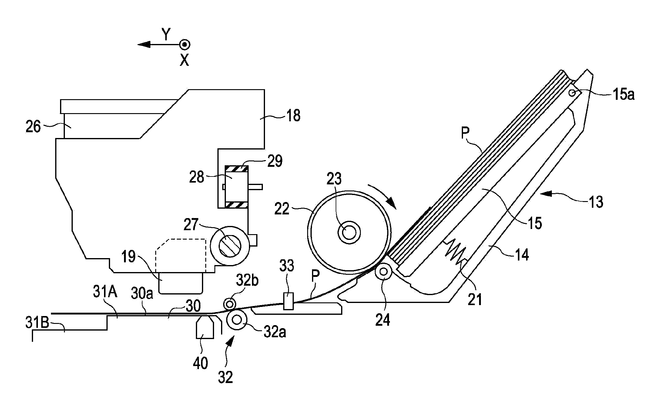
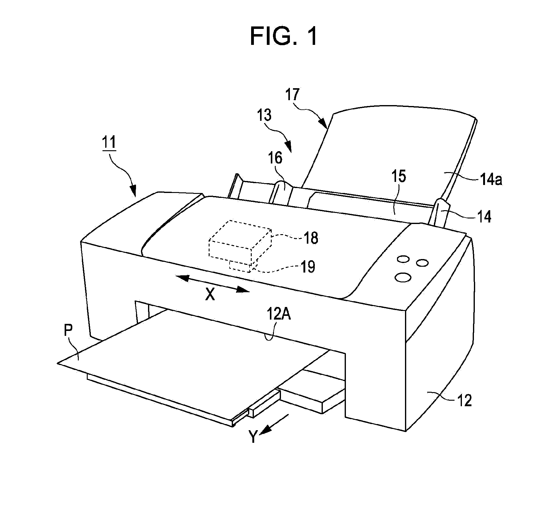
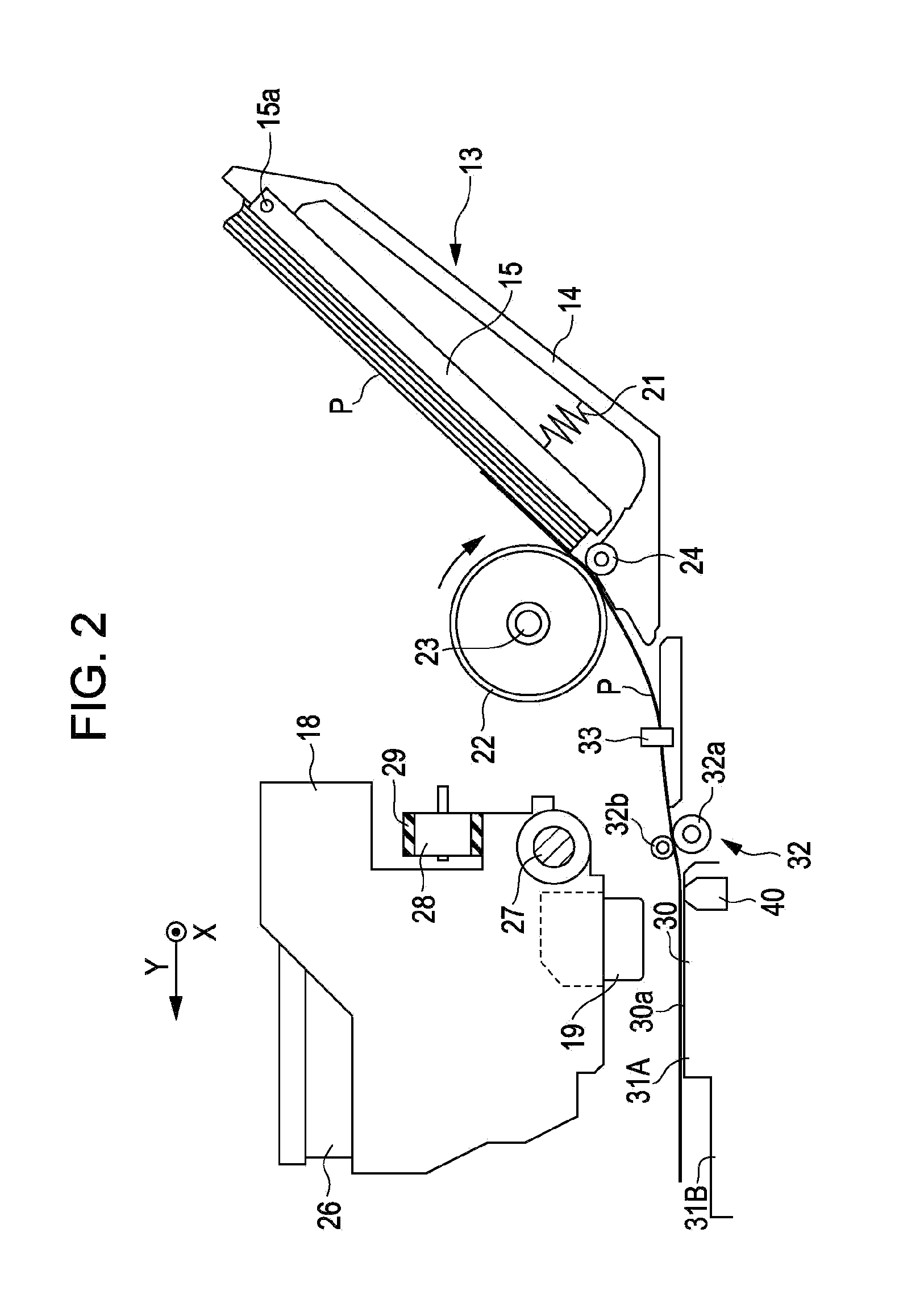
[0033]An embodiment in which a recording apparatus including a medium transportation device according to the invention is implemented as an ink jet printer will be described below with reference to FIGS. 1 to 9. As shown in FIG. 1, the ink jet printer (hereinafter, simply referred to as “printer 11”) as an example of the recording apparatus is provided with an auto sheet feeder 13 on the back of a main body 12 so as to feed paper sheets P as an example of medium. The auto sheet feeder 13 includes a paper sheet guide 17 having a sheet feeding tray 14, a hopper 15, an edge guide 16, and a paper sheet support 14a. The auto sheet feeder 13 feeds the paper sheets that are set on the paper sheet guide 17 one by one into the main body 12.

[0034]A carriage 18 is disposed in the main body 12 so as to reciprocate in a main scan direction X. Further, a recording head 19 is mounted on the underside of the carriage 18. The printer 11 performs printing on the paper sheet P during a transportation ...


PUM


Abstract

A pair of transportation rollers is configured such that a transportation driven roller is disposed at a position which is displaced downstream with respect to a position vertically above a transportation driving roller and feeds out the paper sheet guiding in obliquely downward direction. The entering direction of the paper sheet fed out from the pair of transportation rollers is determined so as to intersect the plane of the holding surface of the support table. A translucent glass that serves as a detection window of an imaging unit disposed at a position opposite to the paper sheet with respect to the holding surface is located downstream in the transportation direction with respect to an intersection position between the entering direction of the paper sheet and the holding surface. Specifically, the translucent glass is located in the proximity of an abutment position where the paper sheet abuts against the holding surface.

Description

BACKGROUND[0001]1. Technical Field[0002]The present invention relates to a medium transportation device that transports media such as sheets of paper for printing and a recording apparatus.[0003]2. Related Art[0004]JP-A-2007-217176 and JP-A-2003-267591 disclose a recording apparatus including a transportation device that transports media (recording media) such as sheets of paper and a recording unit such as a recording head that performs printing on a portion of the medium which is held by a medium holding member while the medium is transported by the transportation device.[0005]In the recording apparatus (image forming device) described in JP-A-2007-217176, the images of the surface feature of the transported medium are sequentially captured by using a camera (imaging device), and two images in a time series are compared so as to calculate the transportation distance of a target pattern in the image. Then, the actual transportation distance of the medium is calculated by summing th...

Claims


Application Information

Patent Timeline
Patent Type & Authority Applications(United States)
IPC IPC(8): B41J11/00
CPCB41J11/00B41J11/0095B41J13/0009B41J13/0018B41J2/01B41J2203/011
Inventor ABE, TAKAHIRO
Owner SEIKO EPSON CORP
Why Eureka
Try Eureka