
Systems and methods for photonic polarization rotators

Active Publication Date: 2013-06-06
SKORPIOS TECH
View PDF28 Cites 21 Cited by
  • Summary
  • Abstract
  • Description
  • Claims
  • Application Information

AI Technical Summary

Benefits of technology

The present invention provides methods and systems for rotating optical polarization in optoelectronics. This capability allows for monolithic integration of polarization diversity receivers in coherent optical receivers or in systems using polarization multiplexing. By using a combination of (45-degree reciprocal and non-reciprocal rotators, devices such as isolators can be implemented on a single substrate. This is important for future generations of low-cost photonic-electronic packages that may have reflective interfaces that would otherwise destabilize the operation of the chip.

Problems solved by technology

Silicon has not been useful for light emission or optical amplification due to its indirect energy bandgap.
This deficiency has prevented the fabrication of monolithically integrated opto-electronic integrated circuits on silicon.
At the same time, integration of advanced electrical functions on these materials has been limited to niche, high-performance applications due to the much higher cost of fabricating devices and circuits in these materials.

Method used


Image

  • Systems and methods for photonic polarization rotators
  • Systems and methods for photonic polarization rotators
  • Systems and methods for photonic polarization rotators

Examples


Embodiment Construction

[0036]Photonic polarization beam splitters integrated on silicon are preferable for the commercial deployment of optoelectronic integrated circuits. Silicon is a preferable material for electronic integration. Silicon technology has advanced such that extremely complex electronic functions can be realized very inexpensively. Embodiments of the present invention relate to systems and methods for integrated photonic polarization beam splitters.

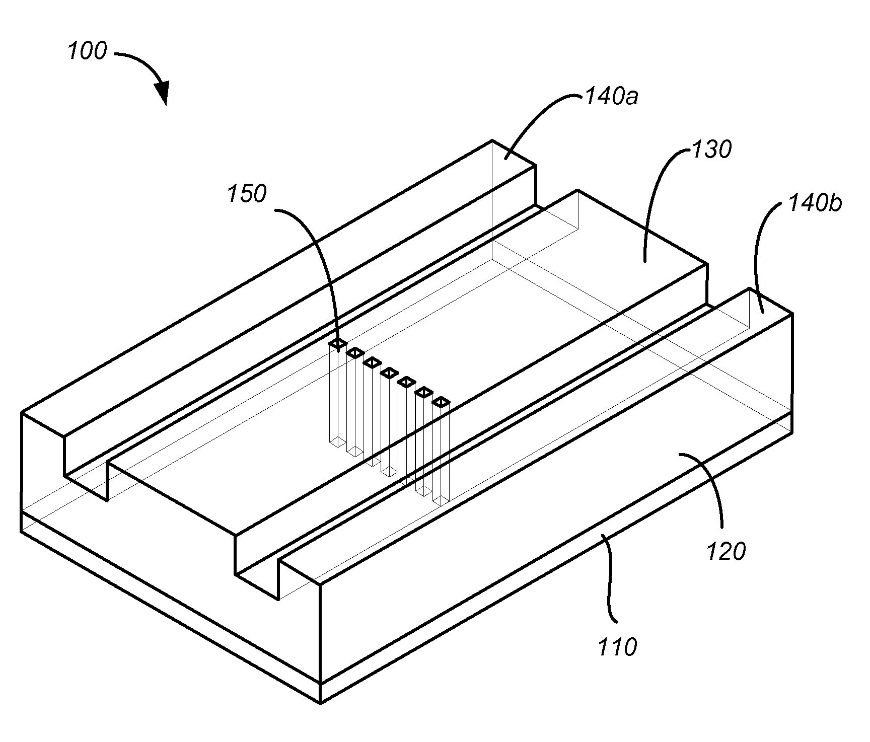
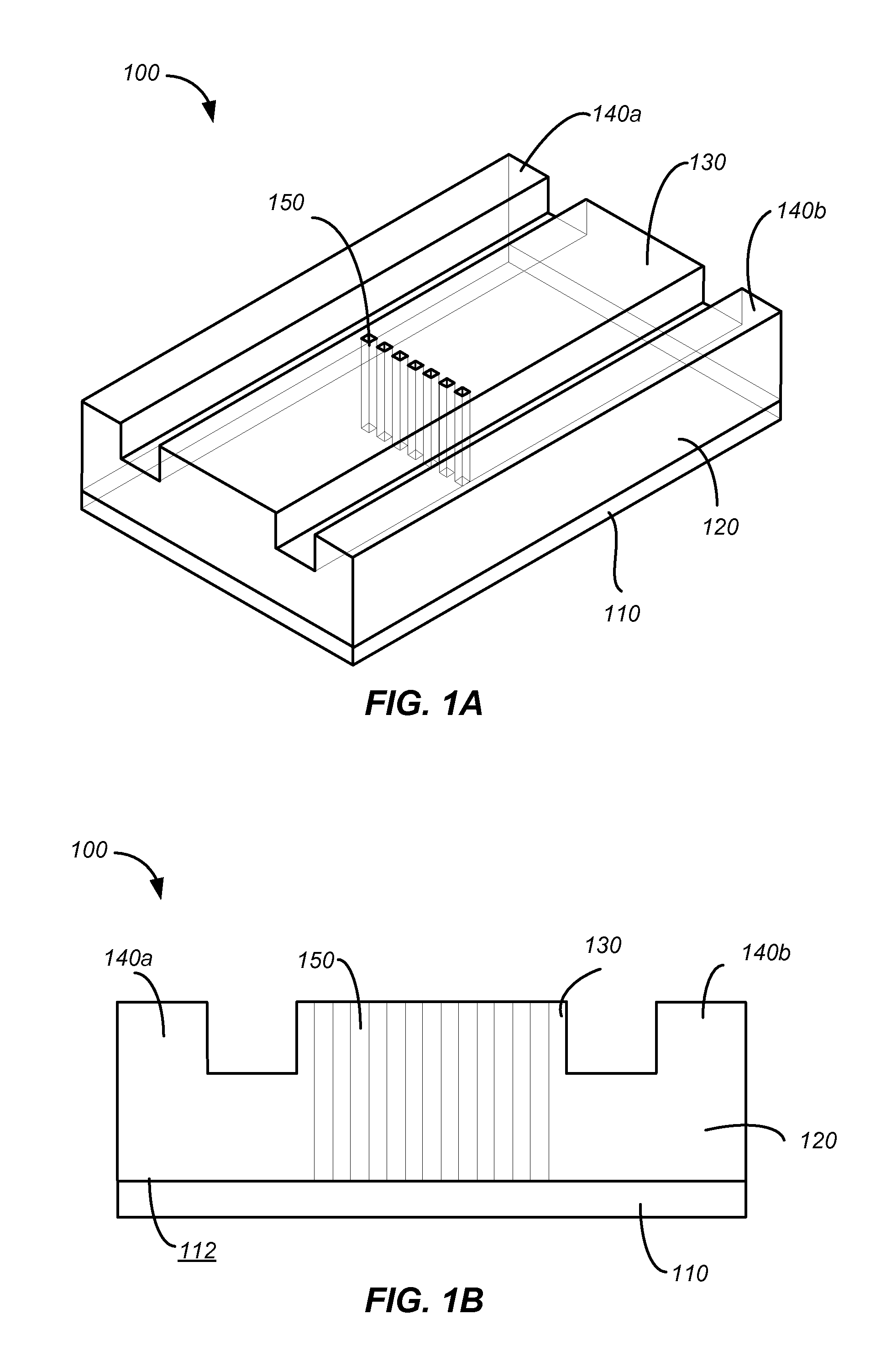
[0037]FIGS. 1A and 1B are a perspective view and a cross-sectional view, respectively, of a simplified schematic diagram illustrating a waveguide polarizer 100 including an array of embedded structures 150 according to an embodiment of the invention. The waveguide polarizer 100 includes a substrate 110 having a surface 112, and a waveguide 120 coupled to the surface 112 of the substrate 110. The waveguide 120 includes a beam propagation portion 130, and two side portions 140a and 140b flanking the beam propagation portion 130. The waveguide pola...


PUM


Abstract

A waveguide polarization rotator includes a substrate having a surface and a waveguide coupled to the surface of the substrate and operable to support a light beam along a direction of beam propagation. The waveguide includes a slab having a support surface and a second surface opposing the support surface and a rib protruding from the second surface of the slab in a direction substantially normal to the surface of the substrate and extending along the direction of beam propagation. The rib includes a first portion extending to a first height above the second surface of the slab and a second portion adjacent to the first portion and extending to a second height above the second surface of the slab. The second height is less than the first height.

Description

CROSS-REFERENCES TO RELATED APPLICATIONS[0001]This application claims the benefit under 35 U.S.C. §119(e) of U.S. Provisional Patent Application No. 61 / 494,871, filed on Jun. 8, 2011, entitled “Method and System for Silicon Photonic Polarization Control,” the disclosure of which is hereby incorporated by reference in its entirety for all purposes.[0002]The following three U.S. Patent Applications (including the present application) are being filed concurrently, and the entire disclosure of the other applications are incorporated by reference into this application for all purposes:[0003]Application No. ______, filed Jun. 7, 2012, entitled “SYSTEMS AND METHODS FOR PHOTONIC POLARIZATION BEAM SPLITTERS” (Attorney Docket No. 92970-808288(000510US));[0004]Application No. ______, filed Jun. 7, 2012, entitled “SYSTEMS AND METHODS FOR PHOTONIC POLARIZATION ROTATORS” (Attorney Docket No. 92970-837395(000520US)); and[0005]Application No. ______, filed Jun. 7, 2012, entitled “SYSTEMS AND METHOD...

Claims


Application Information

Patent Timeline
IPC IPC(8): G02B6/26
CPCG02B6/26G02B6/126G02B5/3058G02B6/105G02F1/0036G02F1/093G02B6/2726G02B6/2746G02B6/2766G02B2006/12061
Inventor DALLESASSE, JOHNKRASULICK, STEPHEN B.
Owner SKORPIOS TECH
Features
  • Generate Ideas
  • Intellectual Property
  • Life Sciences
  • Materials
  • Tech Scout
  • Unparalleled Data Quality
  • Higher Quality Content
  • 60% Fewer Hallucinations
Learn More