Soft cushion structure
a cushioning and soft technology, applied in the field of soft cushion structure, can solve the problems of limited cushioning property, limited construction weight, and inability to meet consumers' needs, and achieve the effects of enhancing comfort performance, efficient distribution, and improving support property
- Summary
- Abstract
- Description
- Claims
- Application Information
AI Technical Summary
Benefits of technology
Problems solved by technology
Method used
Image
Examples
first embodiment
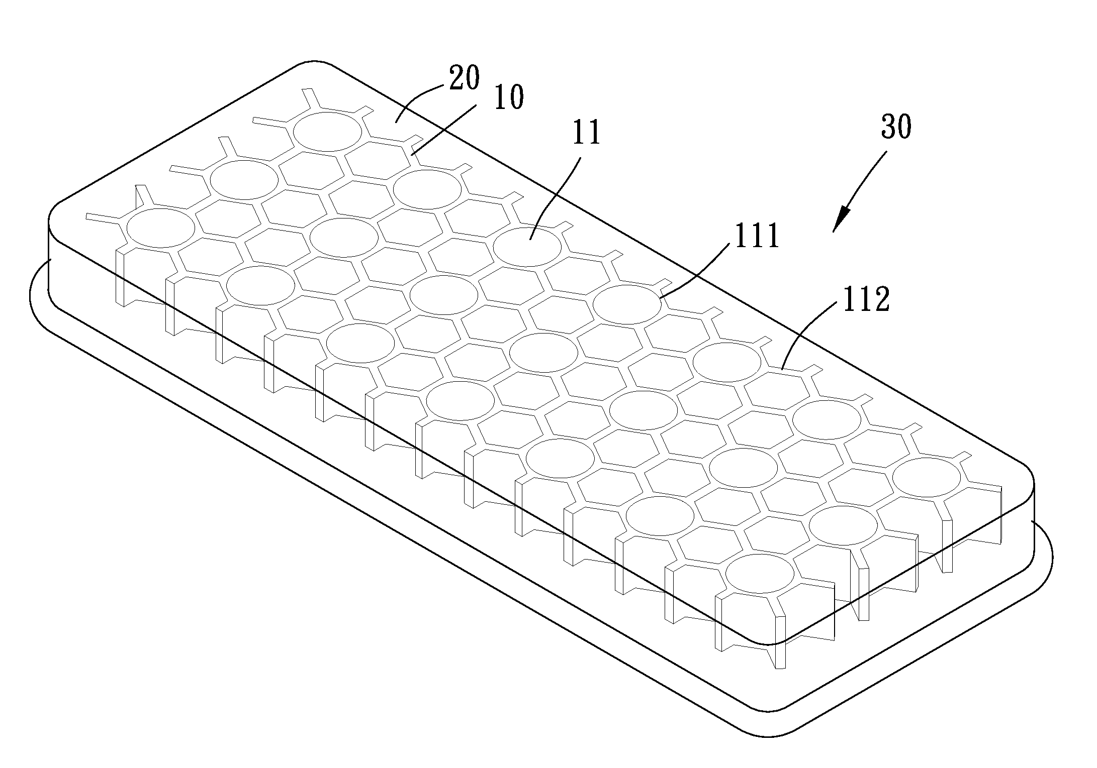
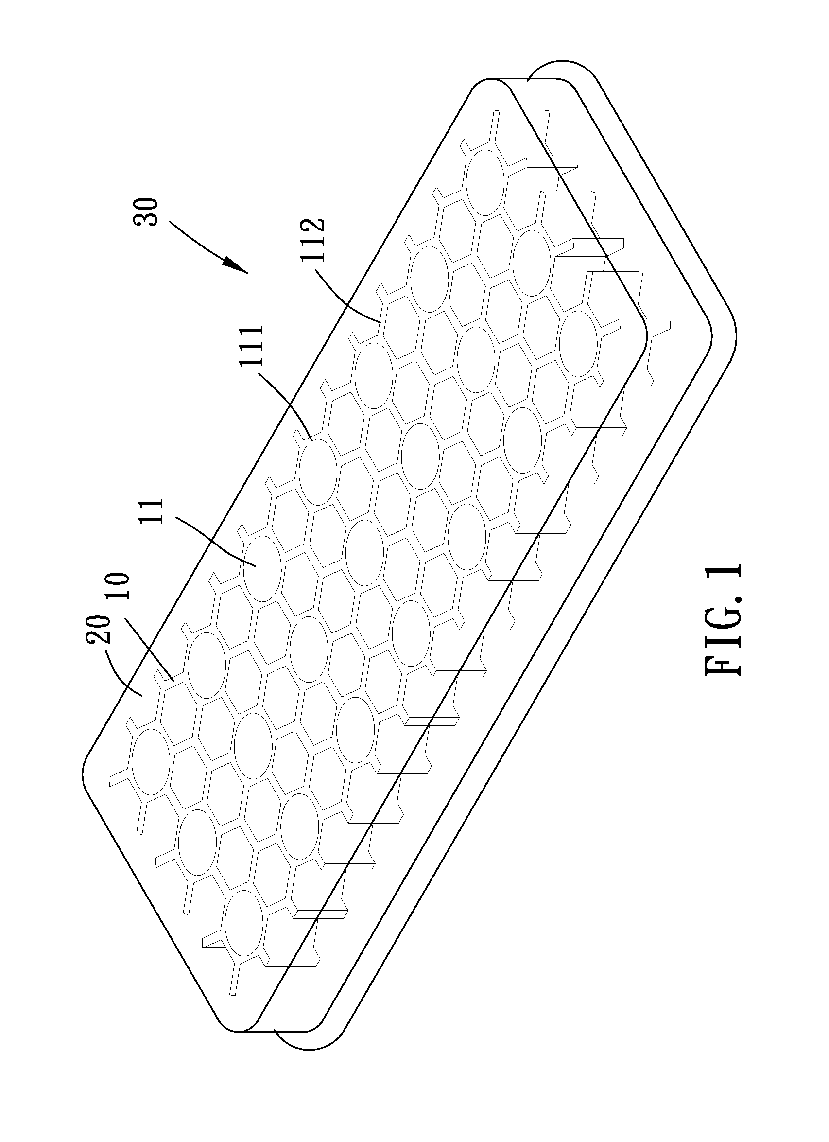
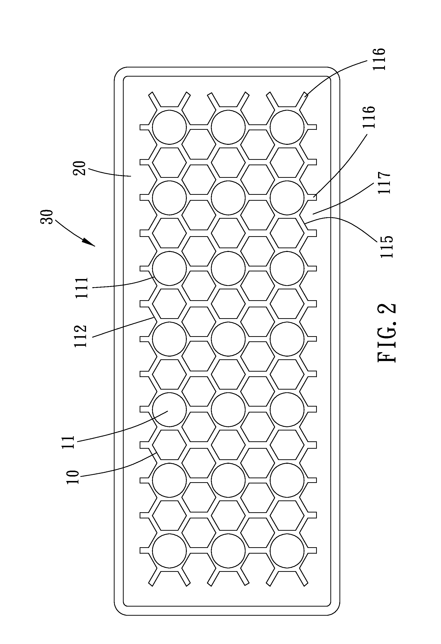
[0021]Please refer to FIGS. 1 to 4 for the present invention. A soft cushion structure includes a soft foaming resilient supportive body 10 and a soft elastomer 20 which is combined with the supportive body 10 to form a composite structure 30.
[0022]The soft foaming resilient supportive body 10 has penetrating holes 11 and a peripheral side wall 115 surrounding the penetrating holes 11 circumferentially. More particularly, the holes 11 penetrate the supportive body 10 in a first direction (along the direction of its thickness) which is traverse to the upper and lower surfaces of the supportive body 10. The supportive body 10 is formed with an upper space 12 and a lower space 13, in which the holes 11 are substantially evenly distributed and communicate the upper and lower spaces 12 and 13. The profile of each holes 11 is circular or other geometric shaped to correspond to the stress or strain requirement of the composite structure 30. As shown in FIG. 3, the supportive body 10 has a ...
second embodiment
[0028]Please refer to FIGS. 6 and 7 for the present invention. In this embodiment, the soft elastomer 20 substantially corresponds to the configure of the foot, and the supportive body 10 has a thenar portion 14, a heel portion 15 and a connecting portion 16 which connects the thenar and heel portions 14 and 15. The thenar portion 14 has several holes 113 corresponding to the toes, and the heel portion 15 has a larger-diametered hole 114 corresponding to the heel. The soft elastomer 20 covers a main part of the upper surface of the supportive body 10, and the soft elastomer 20 is also completely filled in the holes 113 and 114 and laterally extends into the spaces 12 and 13 around the holes 113 and 114. As such, the soft elastomer 20 tightly combines with the supportive body 10 and has sufficient space to enable the slightly flowing strain while being pressed upon. For example, as the user stands on the soft elastomer 20 of the upper space 12, the weight of the user will make the so...
third embodiment
[0030]Refer to FIG. 8 for the present invention. Only one hole 11 is presented on the soft foaming resilient supportive body 10, while the soft elastomer 20 is still filled in the hole 11 and the spaces 12 and 13 so as to combine the soft elastomer 20 with the supportive body 10 to form a composite structure 30. The soft elastomer 20, however, does not fully fill the lower space 13, and a semispherical groove 131 (or other geometric or irregular shaped groove) is left unfilled in the lower space 13. When the composite structure 30 load a compression stress f1, the soft elastomer 20 generates the slightly flowing strain to function the stress-strain compensation mechanism, and a part of the soft elastomer 20 will be pushed into the unfilled semispherical groove 131 to further release the pressure.
[0031]Meanwhile, the supportive body 10 generates the compression strain as well as sheer strain to function the stress-strain compensation mechanism thereof, in which the compression strain...
PUM
 Abstract
Description
Claims
Application Information
 - R&D Engineer
- R&D Manager
- IP Professional
- Industry Leading Data Capabilities
- Powerful AI technology
- Patent DNA Extraction
Browse by: Latest US Patents, China's latest patents, Technical Efficacy Thesaurus, Application Domain, Technology Topic, Popular Technical Reports.
© 2024 PatSnap. All rights reserved.Legal|Privacy policy|Modern Slavery Act Transparency Statement|Sitemap|About US| Contact US: help@patsnap.com


