Speed reduction mechanism, and motor torque transmission device including the same
- Summary
- Abstract
- Description
- Claims
- Application Information
AI Technical Summary
Benefits of technology
Problems solved by technology
Method used
Image
Examples
first embodiment
[0051]Hereinafter, a motor torque transmission device according to the invention will be described in detail with reference to the accompanying drawings.
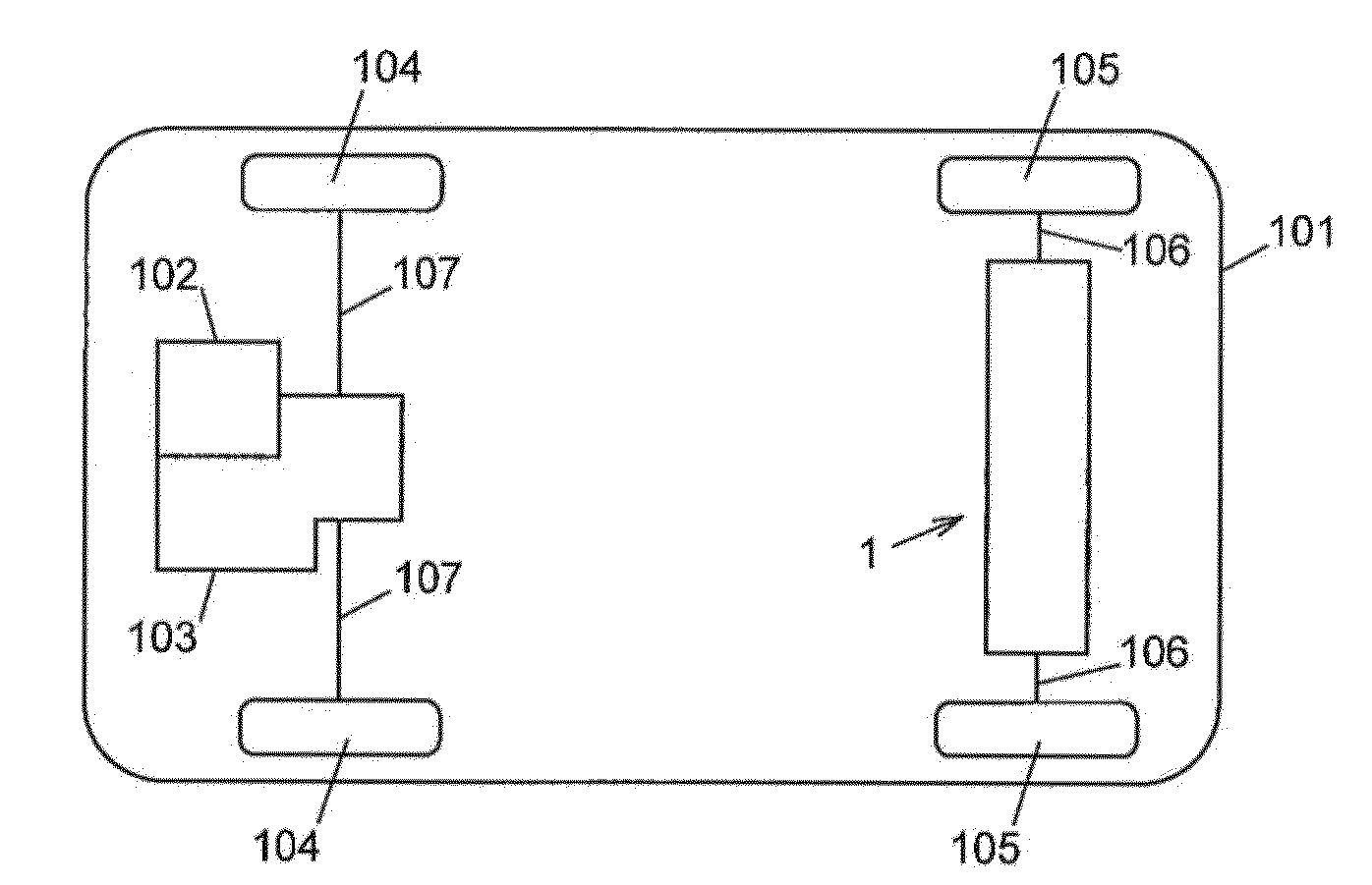
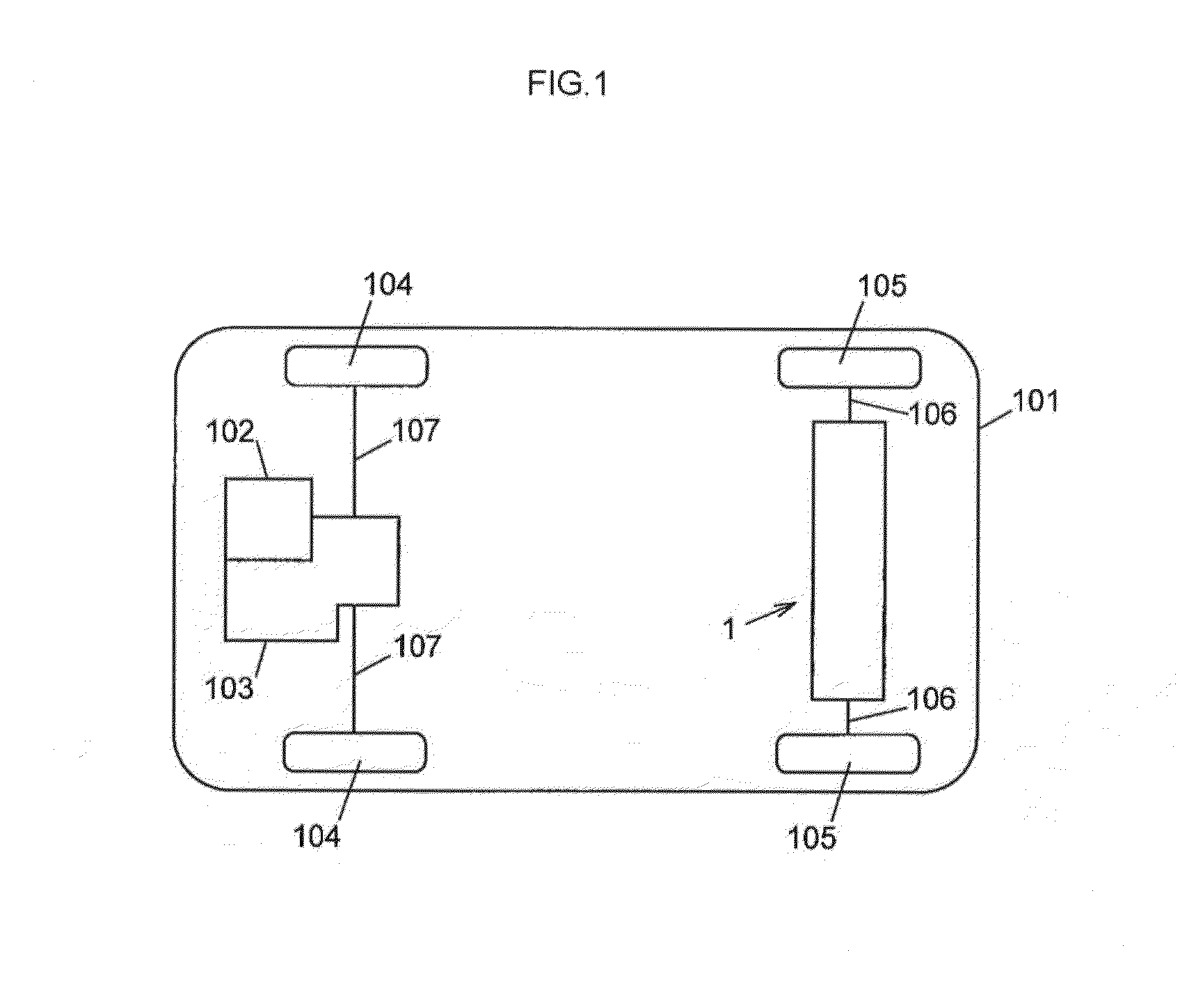
[0052]FIG. 1 schematically shows a four-wheel drive vehicle 101. As shown in FIG. 1, the four-wheel drive vehicle 101 includes a front wheel power system and a rear wheel power system, and includes a motor torque transmission device 1, an engine 102, a transaxle 103, a pair of front wheels 104 and a pair of rear wheels 105. The front wheel power system uses the engine as a driving source. The rear wheel power system uses an electric motor 4 (described later) as a driving source.
[0053]The motor torque transmission device 1 is arranged in the rear wheel power system of the four-wheel drive vehicle 101, and is supported by a vehicle body (not shown) of the four-wheel drive vehicle 101.
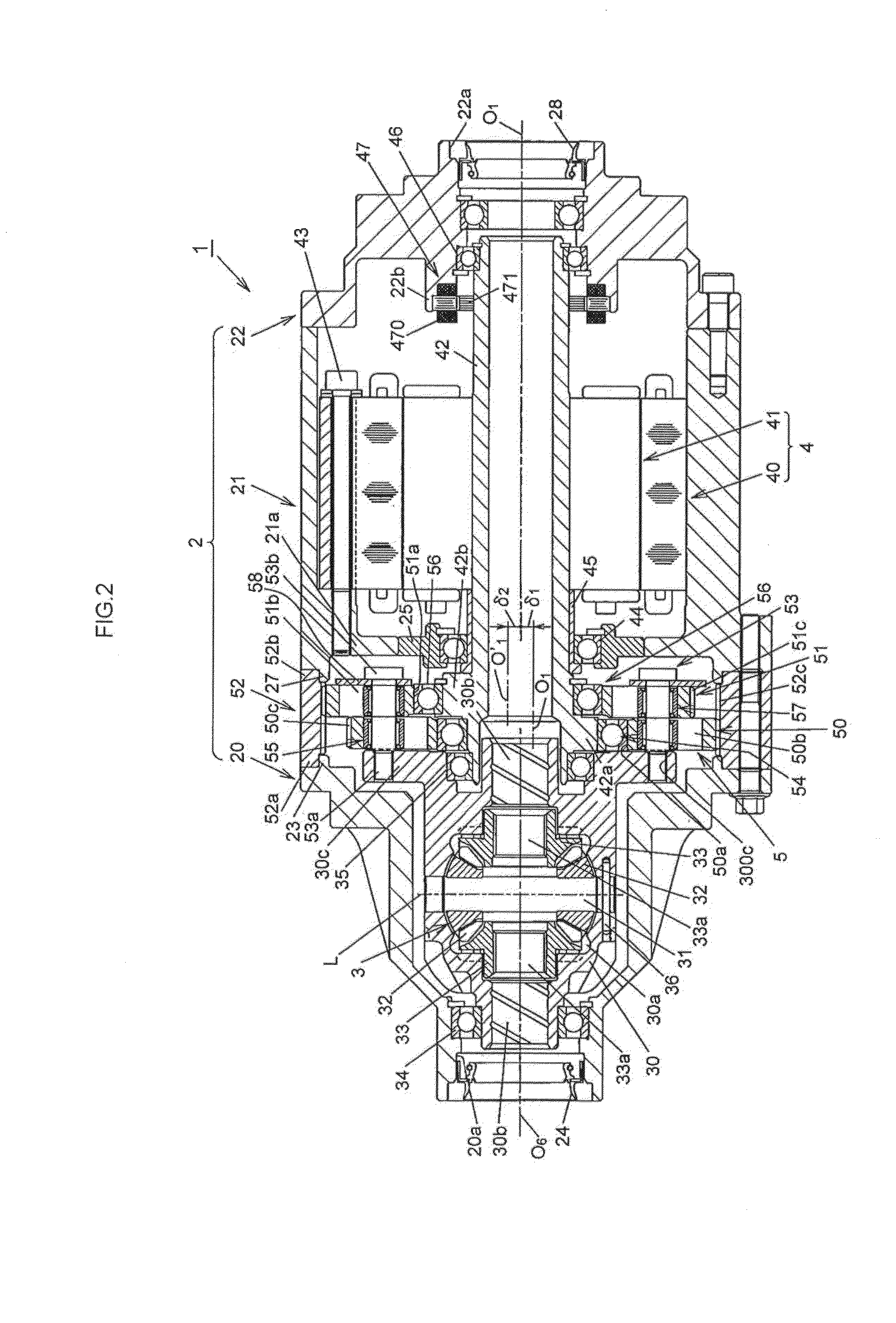
[0054]The motor torque transmission device 1 is configured to transmit driving force based on the motor torque of the electric motor 4 to the rear wheels...
second embodiment
[0115]Next, a speed reduction mechanism in a motor torque transmission device according to the invention will be described with reference to FIG. 9. FIG. 9 shows a state where input members are supported and a state where second bearings are fitted. In FIG. 9, the members having the functions which are the same as or equivalent to those in FIG. 5 are denoted by the same reference numerals are those in FIG. 5, and the detailed description is omitted.
[0116]As shown in FIG. 9, a reduction-transmission mechanism 100 (partially shown) according to the second embodiment of the invention is characterized in that the inner rings 540, 560 of the ball bearings 54, 56 are fitted to the outer peripheries of the eccentric portions 42a, 42b by interference fit, and the outer rings 541, 561 are fitted to the inner peripheries of the input members 50, 51, which define the center holes 50a, 51a, by clearance fit.
[0117]Therefore, on the input member 50 side, if a size obtained by subtracting the outs...
third embodiment
[0127]Next, a speed reduction mechanism in a motor torque transmission device according to the invention will be described with reference to FIG. 10. FIG. 10 shows a state where input members are supported and a state where second bearings are fitted. In FIG. 10, the members having the functions which are the same as or equivalent to those in FIG. 5 are denoted by the same reference numerals are those in FIG. 5, and the detailed description is omitted.
[0128]As shown in FIG. 10, a reduction-transmission mechanism 200 (partially shown) according to the third embodiment of the invention is characterized in that the inner rings 540, 560 of the ball bearings 54, 56 are fitted to the outer peripheries of the eccentric portions 42a, 42b by clearance fit. In addition, the reduction-transmission mechanism 200 is characterized in that the outer rings 541, 561 are fitted to the inner peripheries of the input members 50, 51, which define the center holes 50a, 51a, by interference fit.
[0129]Ther...
PUM
 Abstract
Description
Claims
Application Information
 - R&D
- Intellectual Property
- Life Sciences
- Materials
- Tech Scout
- Unparalleled Data Quality
- Higher Quality Content
- 60% Fewer Hallucinations
Browse by: Latest US Patents, China's latest patents, Technical Efficacy Thesaurus, Application Domain, Technology Topic, Popular Technical Reports.
© 2025 PatSnap. All rights reserved.Legal|Privacy policy|Modern Slavery Act Transparency Statement|Sitemap|About US| Contact US: help@patsnap.com


