Patient transfer device

a technology for transferring devices and patients, applied in nursing beds, medical science, cabinets, etc., can solve the problems of affecting the stability approving the underlying surface on the lower side of the patient support portion, so as to achieve greater spacing, shorter length, and greater length

Inactive Publication Date: 2013-06-13
ARJOHUNTLEIGH
View PDF9 Cites 21 Cited by
  • Summary
  • Abstract
  • Description
  • Claims
  • Application Information

AI Technical Summary

Benefits of technology

[0007]The substantially concave curvature of the lower side of the patient support portion may be formed by joining tethers, e.g., baffles as described in more detail below, between the upper and lower sheets at their areas corresponding to the patient support portion. The tethers may be any suitable structure configured to extend from and interconnect the lower side to the upper side, and may include baffles, straps, or other fasteners, and may be substantially flat or cylindrical. The tethers may delimit and establish the spacing between the upper and lower sheets as the interior volume of the transfer device, including the volume betw

Problems solved by technology

When a patient is supported on the support portion, the patient support portion may bow downwardly and

Method used


Image

  • Patient transfer device
  • Patient transfer device
  • Patient transfer device

Examples


Embodiment Construction

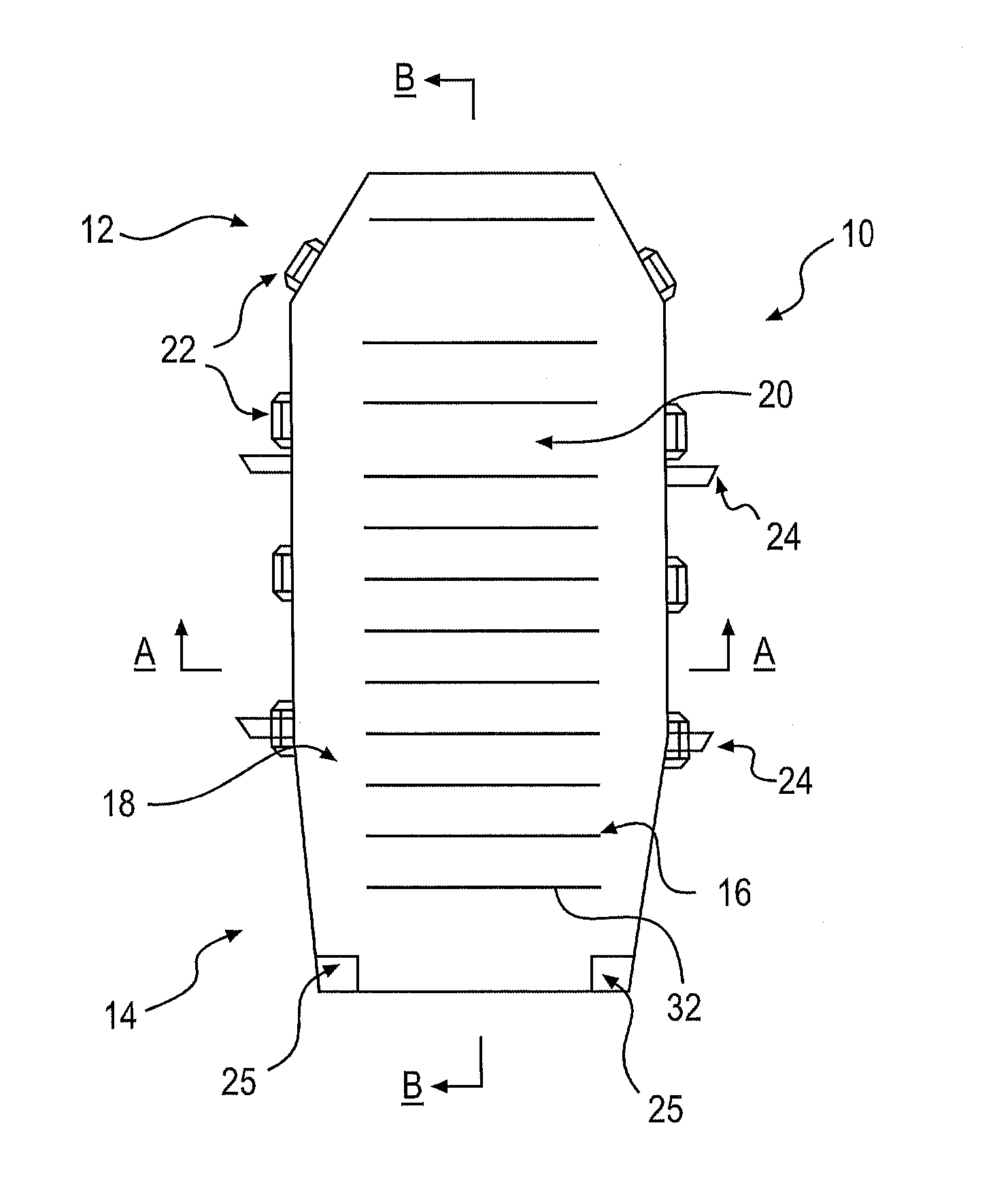
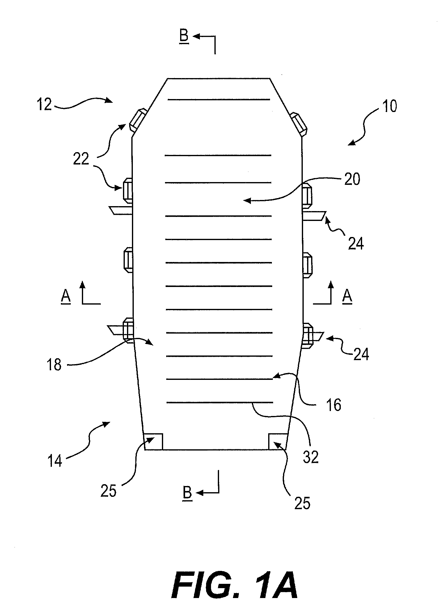
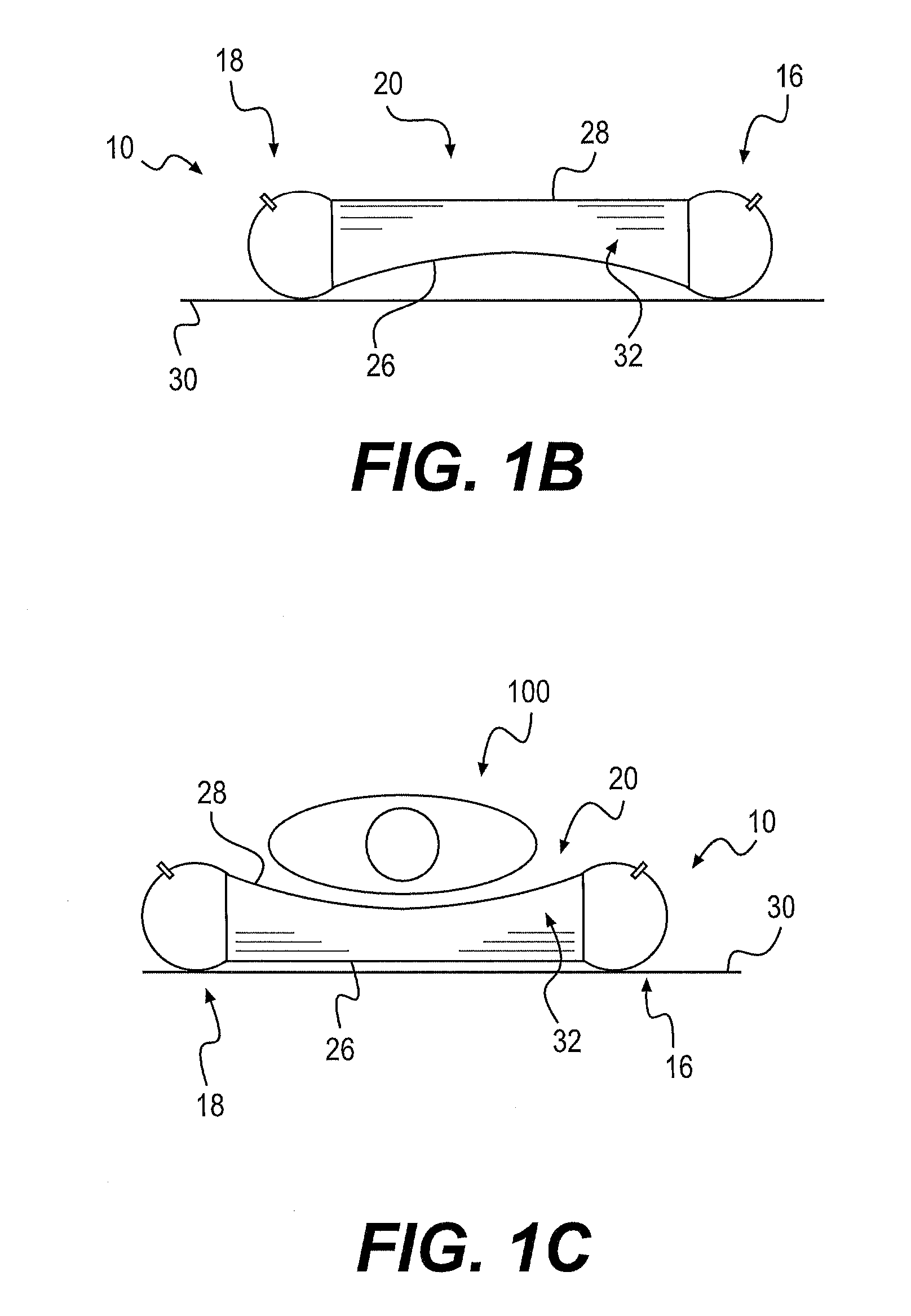
[0017]FIG. 1 illustrates a patient support device 10. The support device 10 may include a head section 12 and a foot section 14 and may also include first and second patient bounding portions 16, 18 disposed generally along lateral sides of the support device 10. The first and second bounding portions or pontoons 16, 18 may extend substantially from the head section 12 to the foot section 14. The support device 10 may also include a patient support portion 20 generally disposed with an inner portion of the device relatively disposed between the bounding portions 16, 18. The support device 10 may be configured as an inflatable mattress assembly or air pallet apparatus, having an internal plenum, for supporting and transferring a patient.

[0018]The support device 10 may also include one or more handles 22 and one or more patient securing straps 24 (only partially shown for clarification purposes, and without their associated buckles or other fasteners). It is contemplated that four han...


PUM


Abstract

A patient support device. The support device includes a first side for contacting a surface, the first side having a perimeter portion and an inner portion. The support device further includes a second side for contacting a patient, the second side having a perimeter portion and an inner portion. The support devices also includes at least one baffle interconnected between the first and second sides. When in an unloaded state, the perimeter portion of the first side is in contact with the surface and the inner portion of the first side is spaced a first distance away from the surface. When in a loaded state the perimeter portion of the first side is in contact with the surface and the inner portion of the first side is spaced a second distance away from the surface. The second distance is less than the first distance.

Description

CROSS-REFERENCE TO RELATED APPLICATIONS[0001]This application claims the benefit of priority from U.S. Provisional Application No. 61 / 568,749, filed Dec. 9, 2011, which is incorporated herein in its entirety.FIELD OF THE DISCLOSURE[0002]This disclosure generally relates to patient transfer devices and, in particular, patient transfer devices for transferring and assisting in transferring patients from one surface to another, e.g., between beds, tables, gurneys, and / or other surfaces in a medical, hospital, and / or other environments.SUMMARY OF THE DISCLOSURE[0003]The disclosure relates to a patient transfer device. The transfer device may include an inflatable mattress or air pallet having a patient support portion for receiving and / or supporting a patient. The transfer device may also include elongated bounding portions bounding the patient support portion at least on opposing sides. The patient support portion has an upper side and an opposing lower side. The lower side may be curv...

Claims


Application Information

Patent Timeline
IPC IPC(8): A61G7/10A61G7/00
CPCA61G7/00A61G2200/32A61G7/1028A61G7/10
Inventor PIEGDON, SAMUELMANUNTA, ALEJANDRO
Owner ARJOHUNTLEIGH
Why Eureka
Try Eureka