Probe for Measuring a Local Angle of Attack and Method Implementing Same
- Summary
- Abstract
- Description
- Claims
- Application Information
AI Technical Summary
Benefits of technology
Problems solved by technology
Method used
Image
Examples
Embodiment Construction
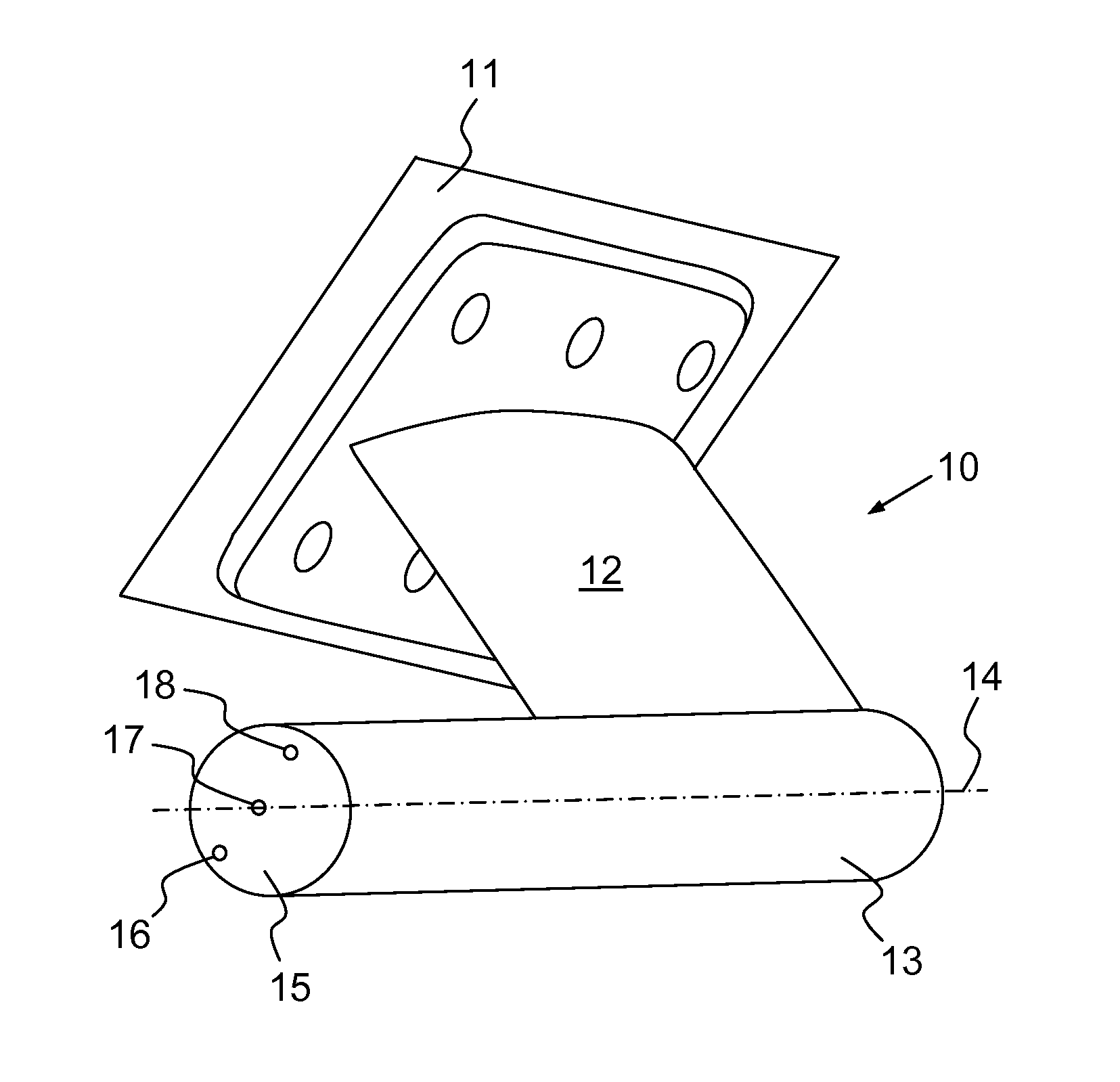
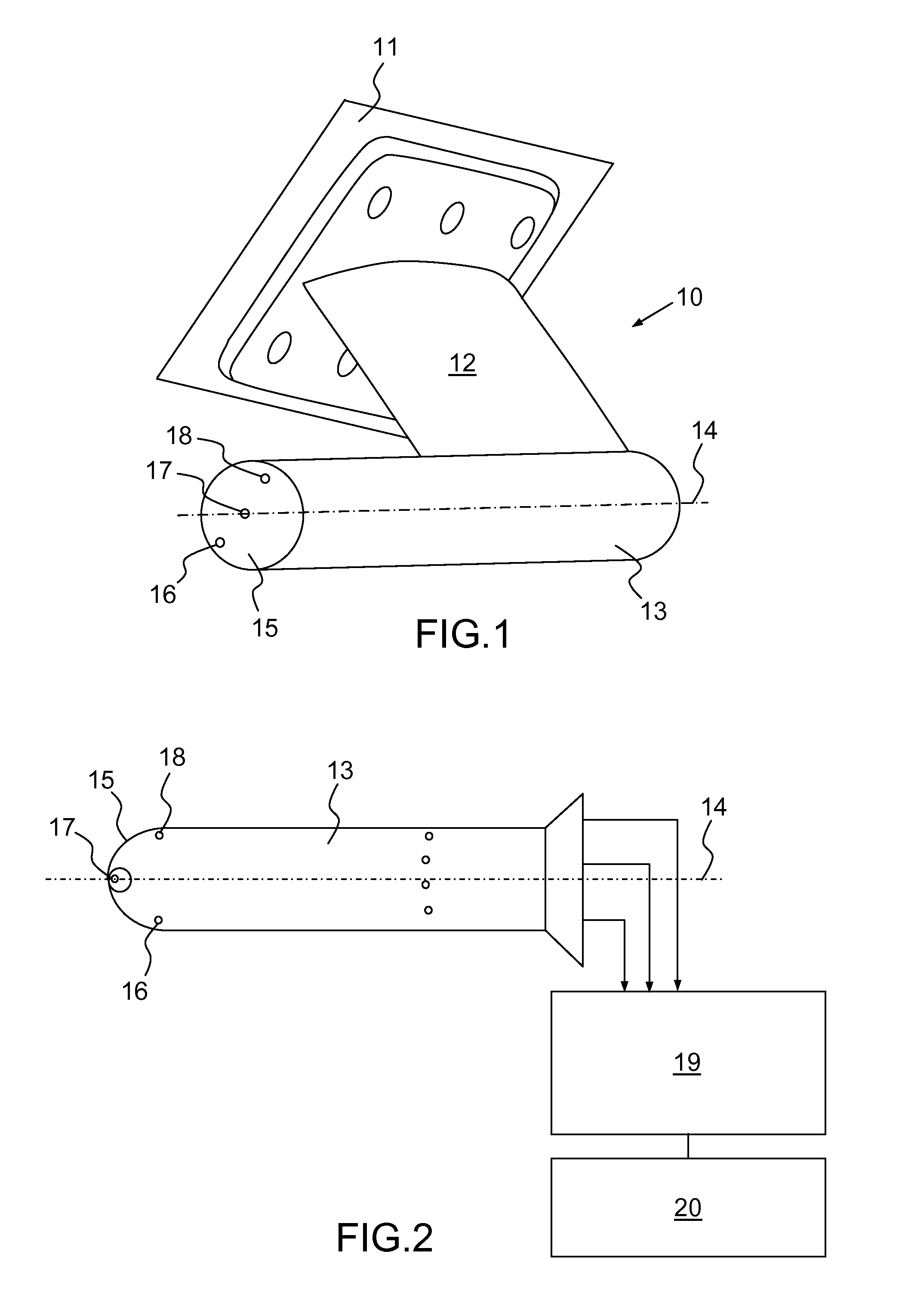
[0021]FIG. 1 shows a probe 10 for measuring a local angle of attack mounted on the skin 11 of an aircraft. The probe 10 allows the angle of attack of the air flowing along the skin 11 to be measured. Such a probe may be positioned at 3 o'clock or at 9 o'clock on the skin of the nose of the aircraft in order to determine the angle of attack of the aircraft. It may also be positioned at 6 o'clock or at 12 o'clock in order to determine the yaw of the aircraft.
[0022]The probe 10 comprises a boom 12 and a probe body 13 fixed to the boom 12. The boom 12 allows the probe body 13 to be positioned outside of a limited layer created in the flow of the air in the immediate vicinity of the skin 11. The boom 12 has, for example, the shape of an aeroplane wing in order to limit the drag in the airflow. The boom 12 is fixed to the skin 11 for example by means of screws. The probe body 13 is for example of cylindrical shape. The probe body 13 is aligned in a main direction 14 which, in the example ...
PUM
 Abstract
Description
Claims
Application Information
 - R&D
- Intellectual Property
- Life Sciences
- Materials
- Tech Scout
- Unparalleled Data Quality
- Higher Quality Content
- 60% Fewer Hallucinations
Browse by: Latest US Patents, China's latest patents, Technical Efficacy Thesaurus, Application Domain, Technology Topic, Popular Technical Reports.
© 2025 PatSnap. All rights reserved.Legal|Privacy policy|Modern Slavery Act Transparency Statement|Sitemap|About US| Contact US: help@patsnap.com


