
Electronic Device with a User Interface that has more than Two Degrees of Freedom, the User Interface Comprising a Touch-Sensitive Surface and Contact-Free Detection Means

a technology of user interface and user interface, which is applied in the direction of cathode-ray tube indicators, instruments, electric digital data processing, etc., can solve the problems of not being able to detect the finger/hand of the user through insulating materials, and touch-sensitive surfaces, etc., to achieve easy learning for users, reduce production costs, and reduce production costs

Active Publication Date: 2013-06-13
MICROCHIP TECH GERMANY II
View PDF8 Cites 123 Cited by
  • Summary
  • Abstract
  • Description
  • Claims
  • Application Information

AI Technical Summary

Benefits of technology

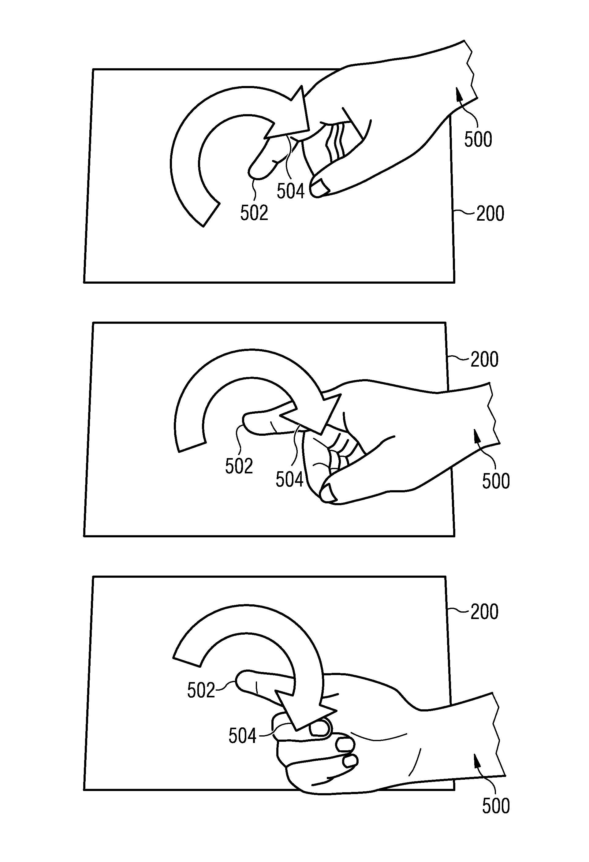
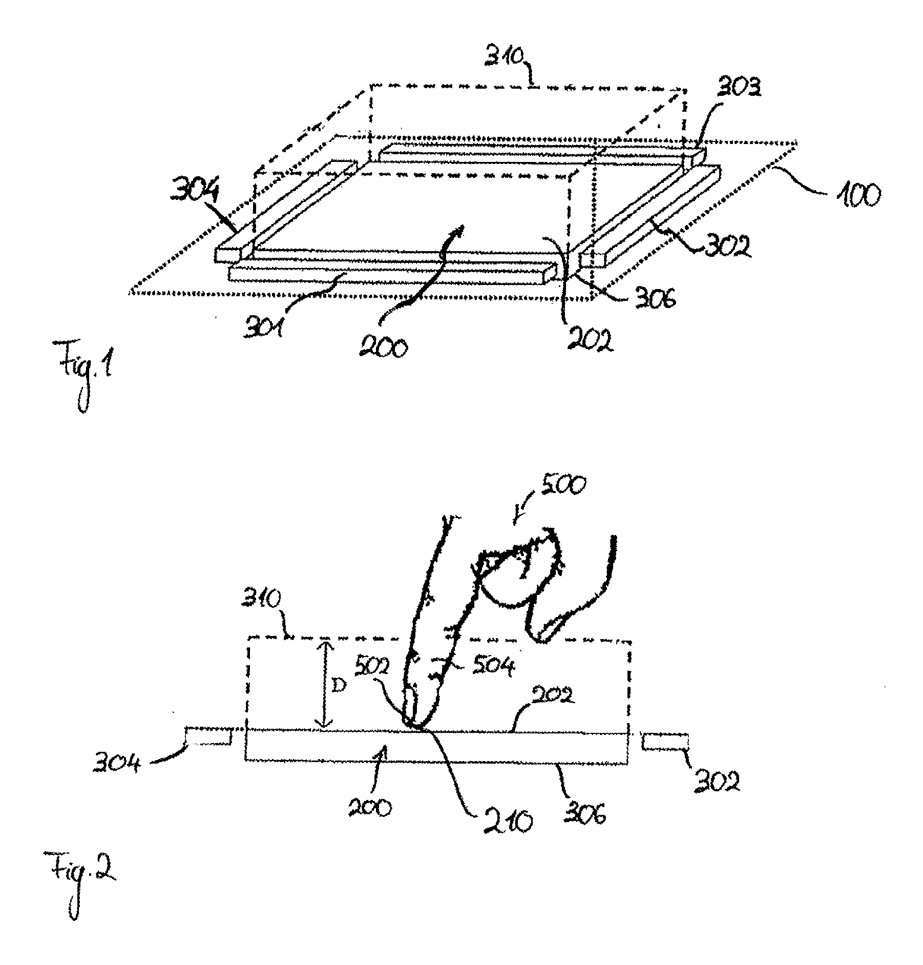
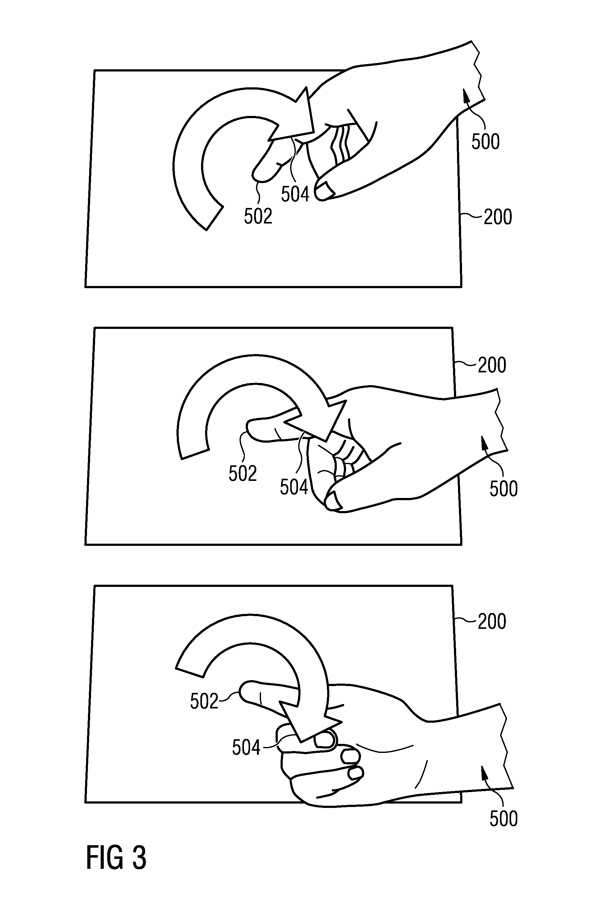
This patent describes an electronic device with a touch-sensitive surface that allows users to interact with it using their fingers or a stylus. The device uses contact-free detection methods that provide additional degrees of freedom by detecting the user's position in relation to the device. These detection methods are seamless with the touch-sensitive surface and do not require any physical contact. The device also has a cylindrical coordinate system that is associated with different gesture categories, making it easier to recognize and perform different tasks with the device.

Problems solved by technology

Further, the sensor technology imposes restraints on what may serve as a user input object.
A touch-sensitive surface based on capacitive sensor technology, for example, cannot detect a user finger / hand through insulating material such as a glove.

Method used


Image

  • Electronic Device with a User Interface that has more than Two Degrees of Freedom, the User Interface Comprising a Touch-Sensitive Surface and Contact-Free Detection Means
  • Electronic Device with a User Interface that has more than Two Degrees of Freedom, the User Interface Comprising a Touch-Sensitive Surface and Contact-Free Detection Means
  • Electronic Device with a User Interface that has more than Two Degrees of Freedom, the User Interface Comprising a Touch-Sensitive Surface and Contact-Free Detection Means

Examples


example electronic device 100

Example Electronic Device 100

[0091]FIG. 7 is a more detailed schematic representation of an example electronic device 100. In this example, which is not to be considered as limiting the invention to the precise forms disclosed, the device 100 includes a memory 102, a memory controller 104, one or more processing modules (CPU's) 106, a peripherals interface 108, RF circuitry 112, audio circuitry 114, a speaker 116, a microphone 118, an input / output (I / O) subsystem 120, a touch-sensitive display 126, contact-free detection means 128, and an external port 148. These components communicate over the one or more communication buses or signal lines 110. The device 100 can be any electronic device, including but not limited to a handheld computer, a tablet computer, a mobile phone, a media player, a personal digital assistant (PDA), or the like, including a combination of two or more of these items. It should be appreciated that the device 100 is only one example of an electronic device 100...


PUM


Abstract

The invention relates to an electronic device for determining a first positional information and a second positional information regarding a user input object, such as at least one user hand or at least one stylus, the electronic device comprising: a touch-sensitive surface; contact-free detection means; and controller means that are operatively connected to the touch-sensitive surface and to the contact-free detection means; wherein the first positional information depends on where the user input object contacts the touch-sensitive surface, and wherein the second positional information depends on the spatial configuration of the user input object with regard to the touch-sensitive surface, characterized in that the controller means are adapted for simultaneously and / or alternately determining the first positional information via the touch-sensitive surface and the second positional information via the contact free detection means.

Description

TECHNICAL FIELD[0001]The disclosed invention in general terms relates to electronic devices with a user interface having more than two degrees of freedom. In particular the invention relates to electronic devices that employ touch-sensitive surfaces, such as trackpads or touch-sensitive displays, as part of their user interfaces.BACKGROUND[0002]Electronic devices with user interfaces in the form of touch sensitive surfaces, such as touchpads and touch-sensitive displays (also referred to as “touch screens” or “touchscreens”), are well known in the art. Touch-sensitive surfaces may serve as a user-interface by detecting a user input object (such as a stylus, a user finger, or a user hand) that touches an active area of the surface. Thereby, the touch-sensitive surface not only detects that an object touches its active area; rather, it also detects where the object makes contact with the active area, i.e., the touch-sensitive display may extract positions (such as x- and y-coordinates...

Claims


Application Information

Patent Timeline
IPC IPC(8): G09G5/00G06F3/041
CPCG06F3/0416G06F2203/04108G06F2203/04106G06F3/044G06F3/041662G06F3/0446G06F3/04883G06F2203/04806G06F3/041
Inventor AUBAUER, ROLANDGEBHARD, ROMAN
Owner MICROCHIP TECH GERMANY II
Learn More