
Holding device for camera and camera device having the same

a technology of holding device and camera, which is applied in the field of camera, can solve the problems of inconvenient user use of camera, troublesome or dangerous holding the camera by hand, and inability to fix the camera to a user,

Inactive Publication Date: 2013-06-13
SHENZHEN AEE TECH
View PDF2 Cites 15 Cited by
  • Summary
  • Abstract
  • Description
  • Claims
  • Application Information

AI Technical Summary

Benefits of technology

The present invention provides a holding device for cameras that allows users to operate the camera without detaching the whole holding device from the mounting point. The detachable mounting components of the holding device make it easy to replace one component without replacing the entire holding device, reducing production and usage costs. The lockable engagement between the inserting member and the base allows the camera to be operated without detaching the holding device. The rotating connection between the connecting member and the rotating member allows the camera to take pictures from various angles, which can be fixed using a screw bolt.

Problems solved by technology

However, the present camera cannot be fixed to a user when necessary, thus, the user has to take pictures by holding the camera at hand.
However, in some special situations, for example, when the user is climbing mountains, doing mining jobs, or driving a car, holding the camera by hand may be troublesome or dangerous.
Although there are some holding devices can be used for holding the camera, if the user want to operate the camera after the camera is held in the holding device, the user has to detach the camera as well as the holding device away from the mounting point for operating the camera, which is inconvenient for the user to use the camera.
Additionally, it is difficult to dissemble the components of the holding device.

Method used


Image

  • Holding device for camera and camera device having the same
  • Holding device for camera and camera device having the same
  • Holding device for camera and camera device having the same

Examples


Embodiment Construction

[0026]The disclosure is illustrated by way of example and not by way of limitation in the figures of the accompanying drawings in which like references indicate similar elements. It should be noted that references to “an” or “one” embodiment is this disclosure are not necessarily to the same embodiment, and such references mean at least one.

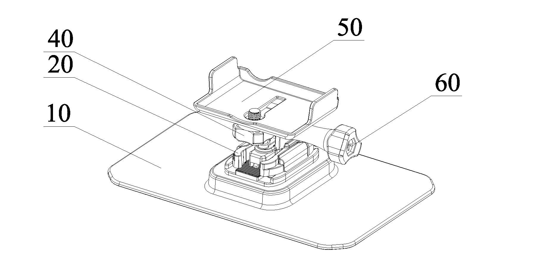
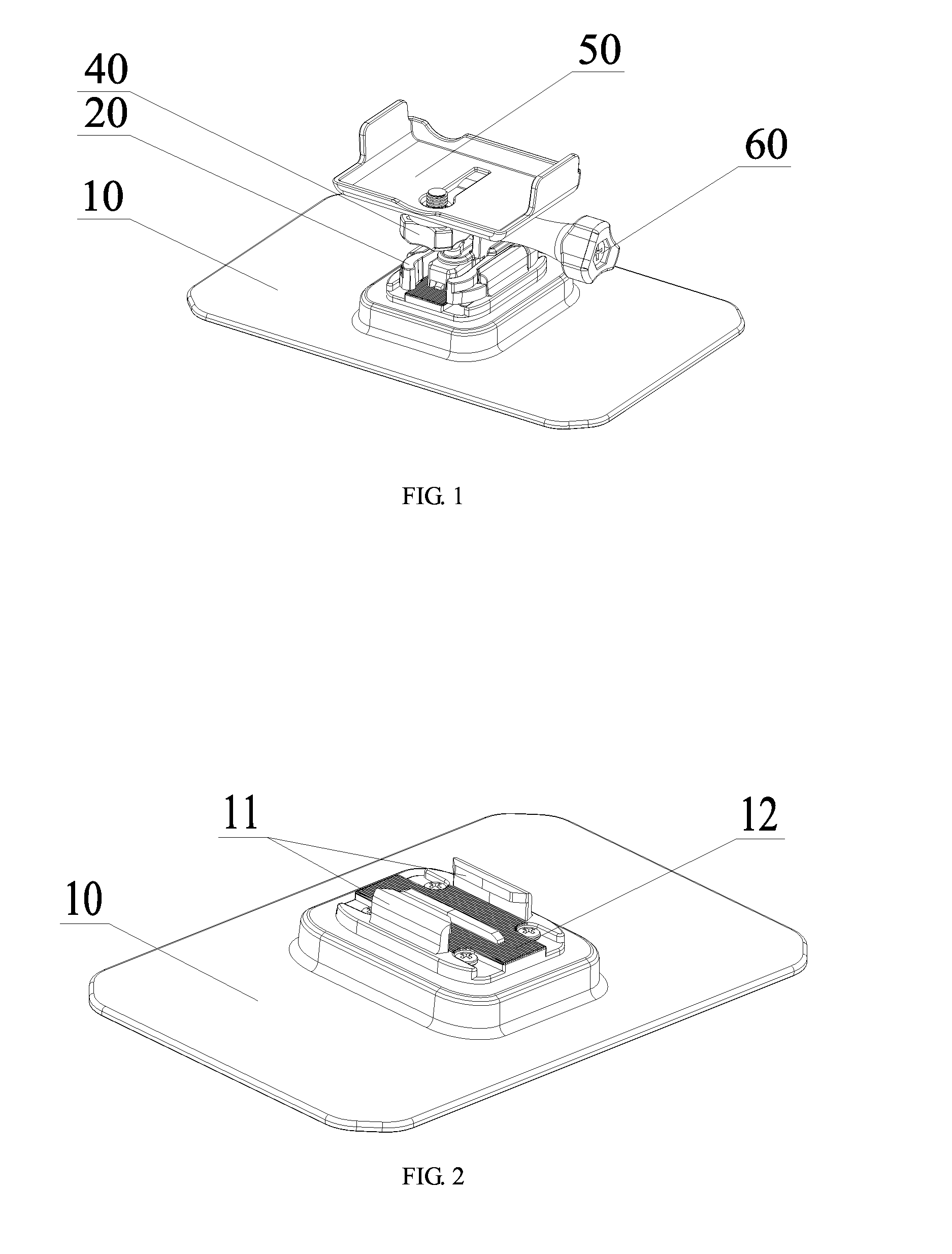
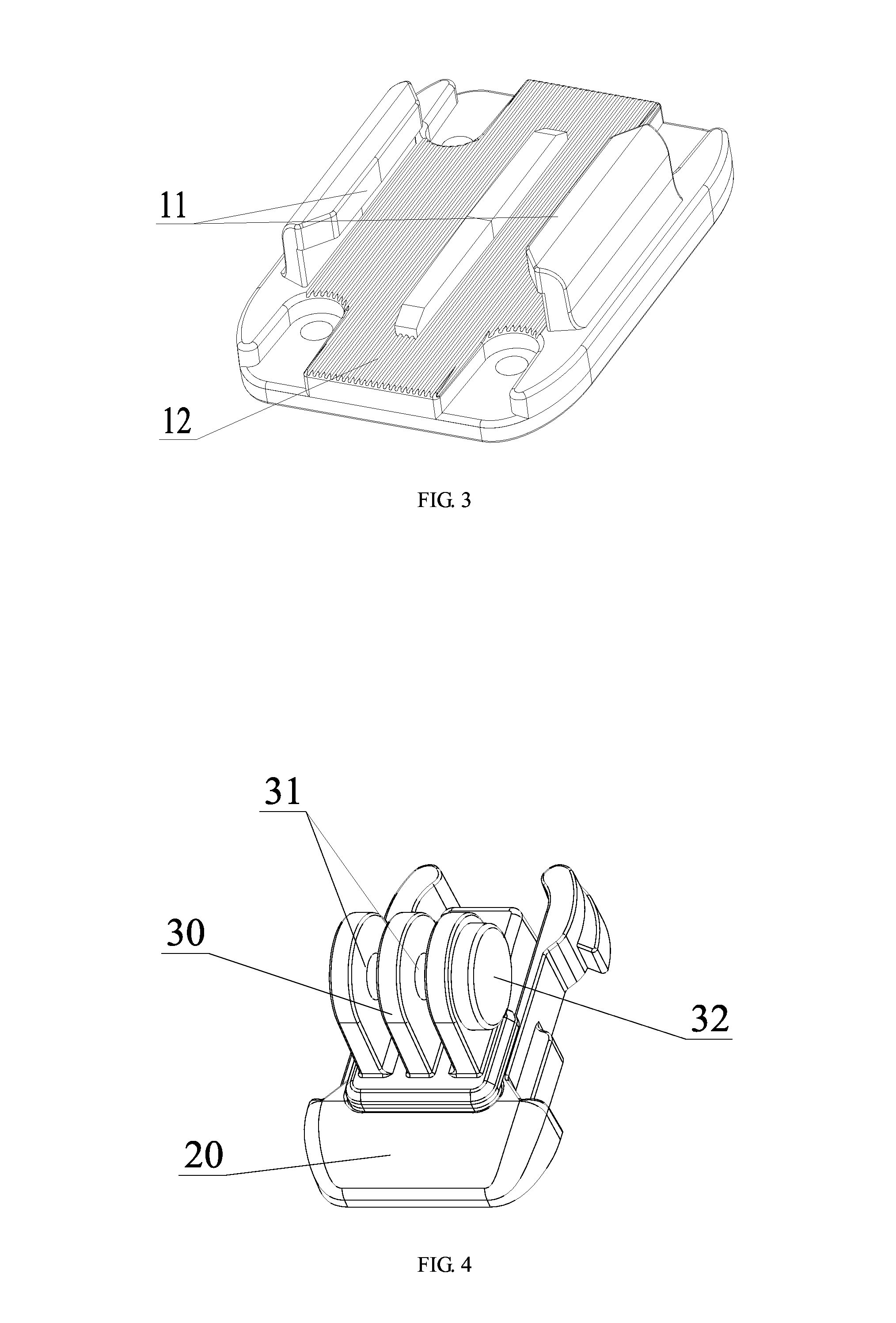
[0027]Referring to FIGS. 1 to 3, in which FIG. 1 is a schematic view of a holding device for a camera in accordance with an embodiment of the present disclosure, FIG. 2 is a schematic view of a base of the holding device of FIG. 1, and FIG. 3 is a an partially enlarged view of the base.

[0028]The holding device for a camera includes a base 10, an inserting member 20, a connecting member 30, a rotating member 40, a mounting member 50, and a screw bolt 60. A limiting slot 11 engageable with the inserting member 20 is arranged on an upper surface of the base 10. A first wire slot structure 12 is formed on the bottom portion of the limiting slot 11 an...


PUM


Abstract

A holding device for a camera includes a base and an inserting member; the base includes a limiting slot and a first wire slot formed on a bottom portion of the limiting slot; the inserting member is inserted to the limiting slot to engage with the limiting slot; the inserting member includes a second wire slot formed on a side thereof which contacts the limiting slot, and the second wire slot engages with the first wire slot after the inserting member is inserted into the limiting slot to engage with the limiting slot. The holding device of the present disclosure not only allows a user to mount a camera to hamlets, walls, or planes, but also avoids the situation where the whole holding device needs to be replaced when one of the above components is damaged.

Description

BACKGROUND[0001]1. Technical Field[0002]The present disclosure relates to cameras and, particularly, to a holding device for a camera and a camera device having the same.[0003]2. Description of Related Art[0004]With the development of technology, cameras are commonly used. At present, cameras are powerful and can be used for different purposes. However, the present camera cannot be fixed to a user when necessary, thus, the user has to take pictures by holding the camera at hand. However, in some special situations, for example, when the user is climbing mountains, doing mining jobs, or driving a car, holding the camera by hand may be troublesome or dangerous. Although there are some holding devices can be used for holding the camera, if the user want to operate the camera after the camera is held in the holding device, the user has to detach the camera as well as the holding device away from the mounting point for operating the camera, which is inconvenient for the user to use the c...

Claims


Application Information

Patent Timeline
IPC IPC(8): G03B17/00G03B17/56
CPCG03B17/00F16M11/10F16M11/041G03B17/561
Inventor ZHANG, XIANZHI
Owner SHENZHEN AEE TECH
Learn More