Boundary layer controlled logarithmic spiral blade

Active Publication Date: 2013-06-13
MCAFEE INC +1
View PDF2 Cites 14 Cited by
  • Summary
  • Abstract
  • Description
  • Claims
  • Application Information

AI Technical Summary

Problems solved by technology

However, none of the above-mentioned structures provide a naturally fluid pathway, mating the blades' design and shape, for increasing air flow pressure and thereby reducing inefficiencies generated by flow separations along surfaces of the blades.

Method used


Image

  • Boundary layer controlled logarithmic spiral blade
  • Boundary layer controlled logarithmic spiral blade
  • Boundary layer controlled logarithmic spiral blade

Examples


Embodiment Construction

[0023]Embodiments of the present invention will be described hereinafter with reference to the accompanying drawings, in which preferred exemplary embodiments of the invention are shown. The ensuing description is not intended to limit the scope, applicability or configuration of the disclosure. Rather, the ensuing description of the preferred exemplary embodiments will provide those skilled in the art with an enabling description for implementing preferred exemplary embodiments of the disclosure. It should be noted that this invention may be embodied in different forms without departing from the spirit and scope of the invention as set forth in the appended claims.

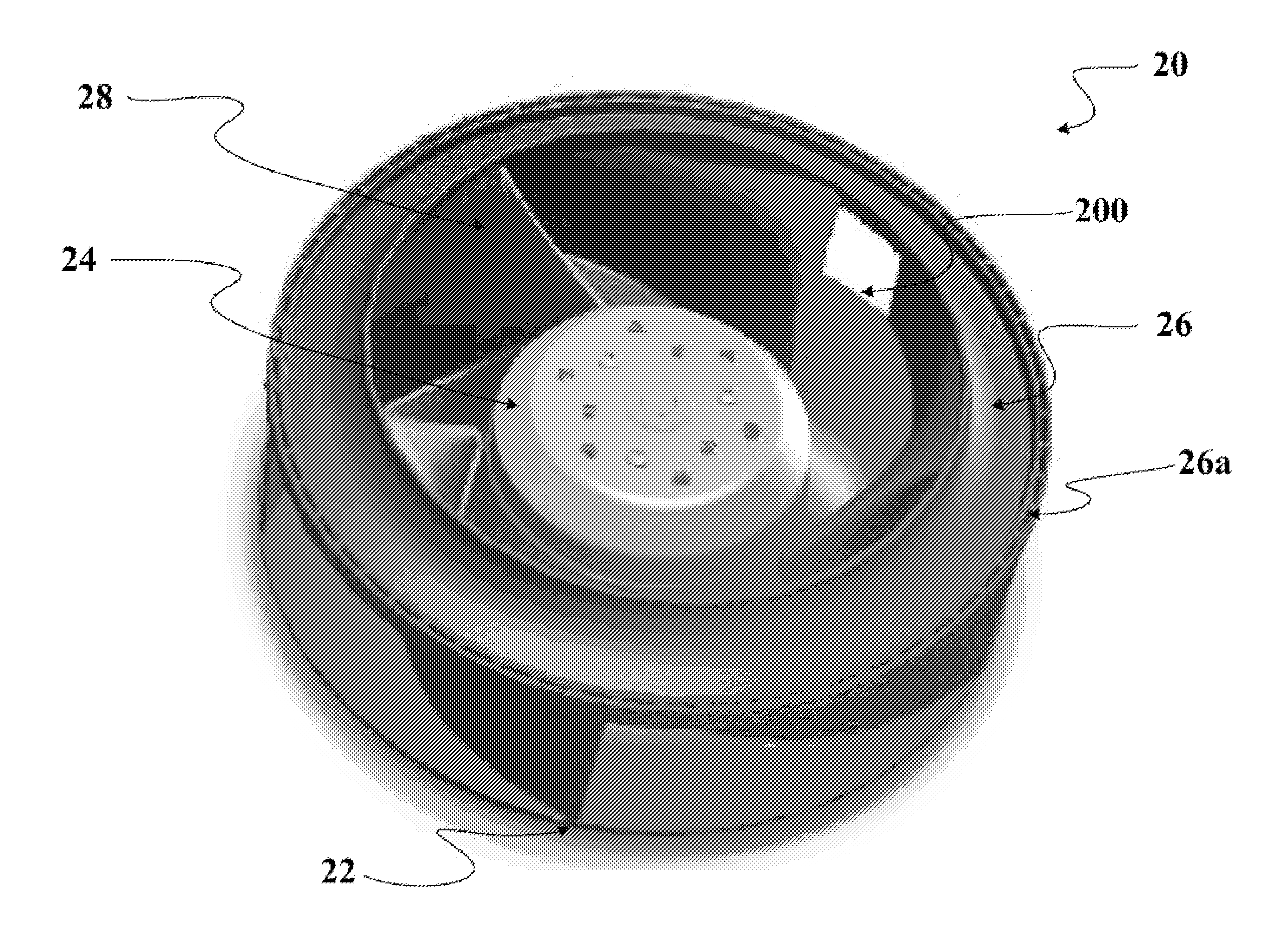
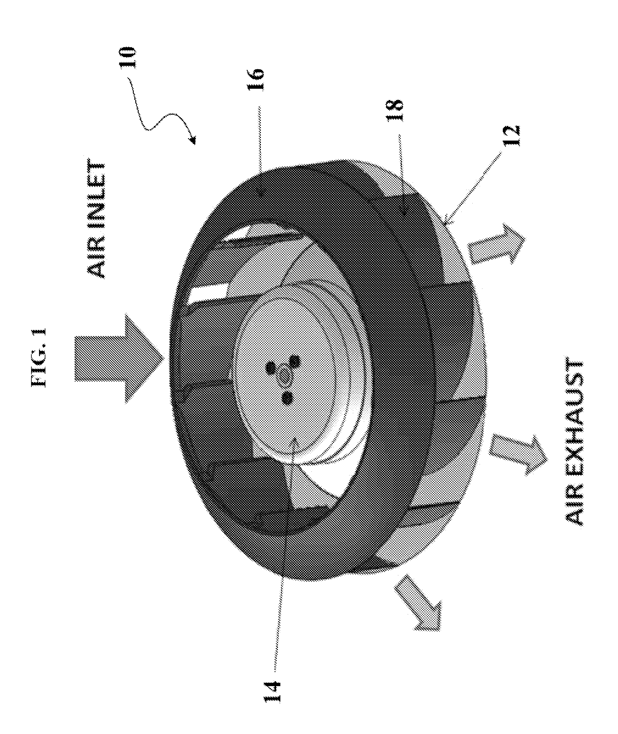
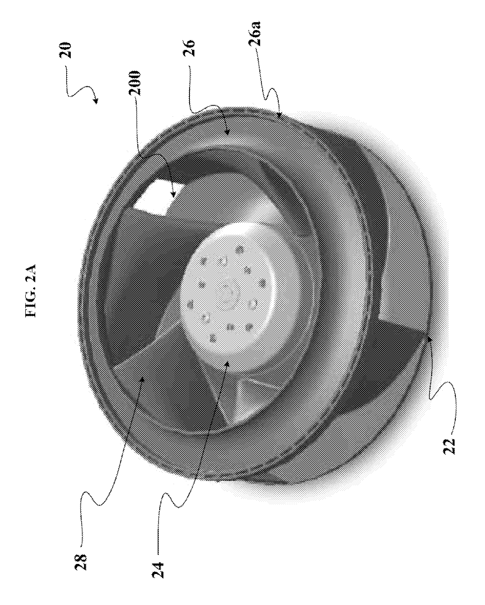
[0024]This disclosure relates in general to centrifugal fans disposed with an impeller. More specifically, it relates to a new design and orientation of impeller blades for improving the P-Q characteristics and the efficiency of the centrifugal fans.

[0025]Embodiments of the present invention are directed to a new and impr...


PUM


Abstract

An impeller structure for a centrifugal fan apparatus includes a circular back plate, a ring-shaped shroud, and a tubular hub. The ring-shaped shroud and the tubular hub are respectively located a predetermined distance above and at the center of said circular back plate. The impeller structure further includes a plurality of blades which are annularly disposed around the tubular hub between the circular back plate and the ring-shaped shroud. Each of the plurality of blades includes a chord with a logarithmic spiral shape, and a mean camber line with an angle of return against the chord.

Description

TECHNICAL FIELD[0001]The present invention relates to an impeller of a centrifugal fan and to a centrifugal fan disposed with the impeller. More specifically, it relates to a new design and orientation of impeller blades for improving the P-Q characteristics and efficiency of the centrifugal fan.BACKGROUND OF THE INVENTION[0002]High performance fans are used in variety of industrial and laboratory applications such as, for example, heating, ventilating, and cooling systems. The performance and desirability of the fans are measured by the fan efficiency and acoustic level produced during operation. The improvement of fan efficiency will reduce the energy needed to operate the fan and / or increase output airflow and pressure.[0003]Fan efficiency is affected by a number of factors. For example, the efficiency of a drive mechanism such as a motor and the revolving speed of the motor and blades may impact the fan energy efficiency. Another example of efficiency factors may include the cle...

Claims


Application Information

Patent Timeline
Patent Type & Authority Applications(United States)
IPC IPC(8): F01D5/22
CPCF01D5/186F01D5/20Y02T50/676F04D29/30F04D29/281Y02T50/60
Inventor SHOJI, HIROFUMI
Owner MCAFEE INC
Why Eureka
Try Eureka