Cannula ring and related systems and methods

a technology of cannula and ring, applied in the field of cannula rings, can solve the problems of various difficulties in connecting a conduit assembly with the heart, and achieve the effect of improving the service life and improving the service li

Active Publication Date: 2013-06-13
WORLD HEART
View PDF5 Cites 33 Cited by
  • Summary
  • Abstract
  • Description
  • Claims
  • Application Information

AI Technical Summary

Problems solved by technology

However, various difficulties may present themselves in connecting a conduit assembly with the heart.

Method used


Image

  • Cannula ring and related systems and methods
  • Cannula ring and related systems and methods
  • Cannula ring and related systems and methods

Examples


Embodiment Construction

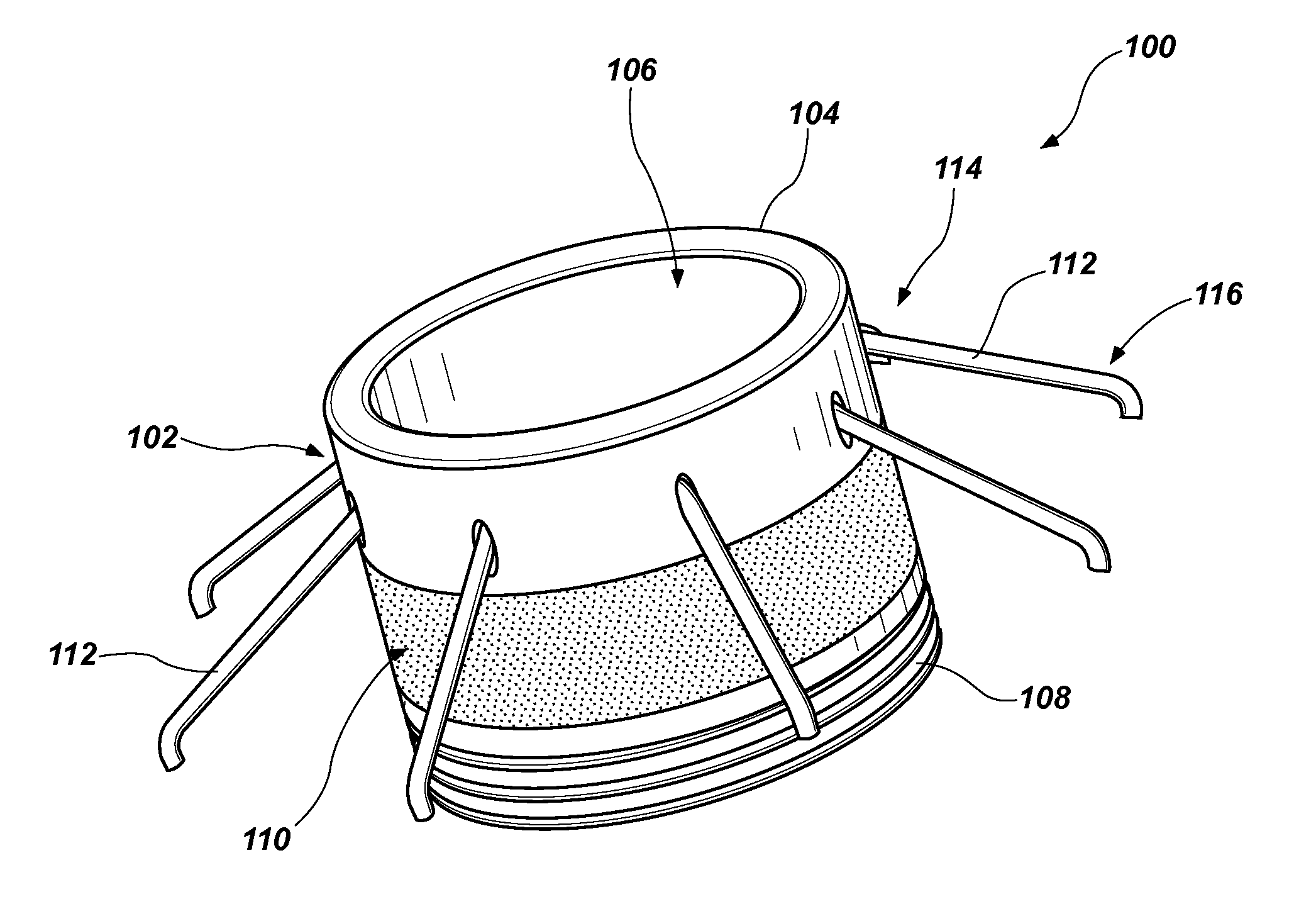
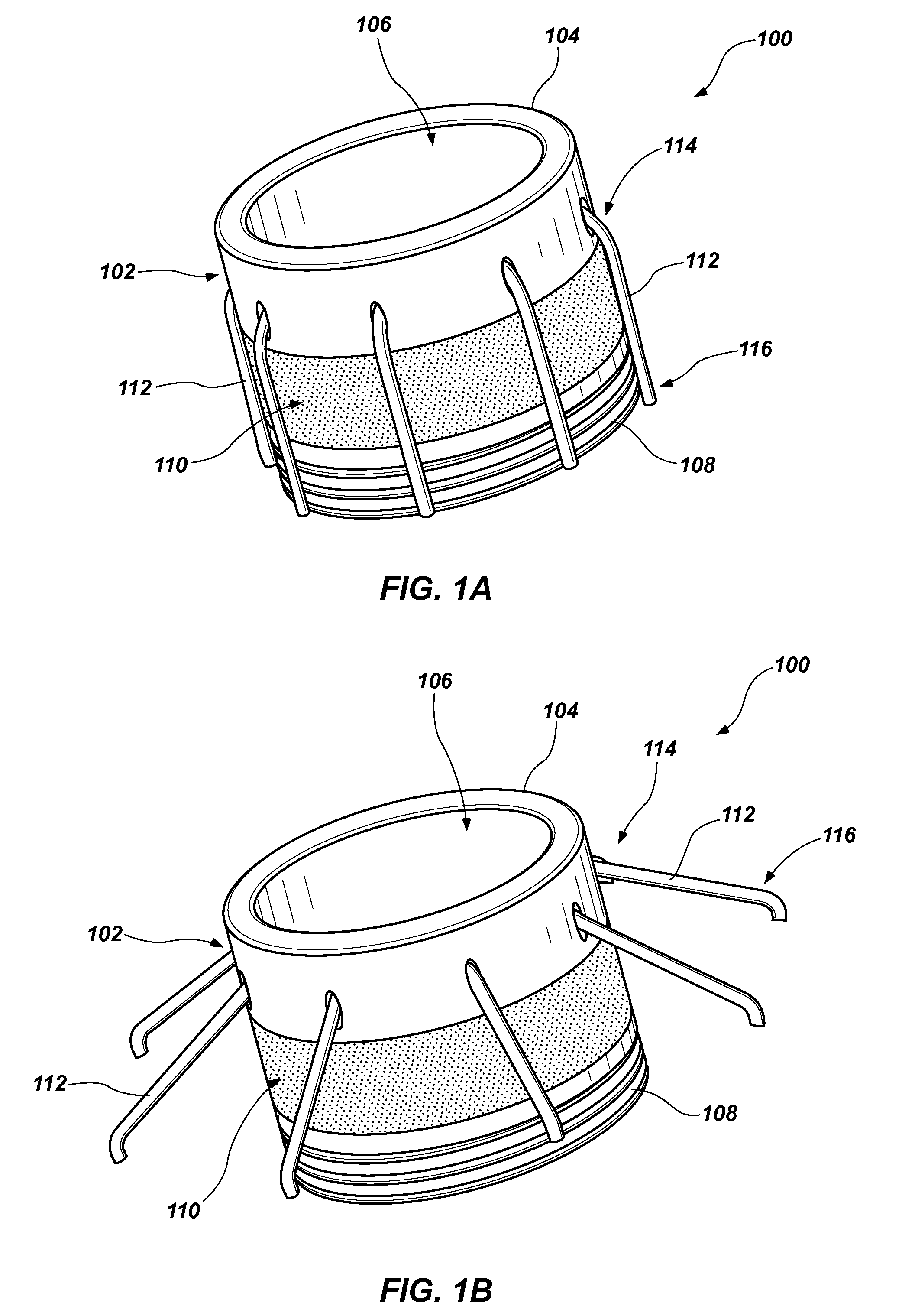
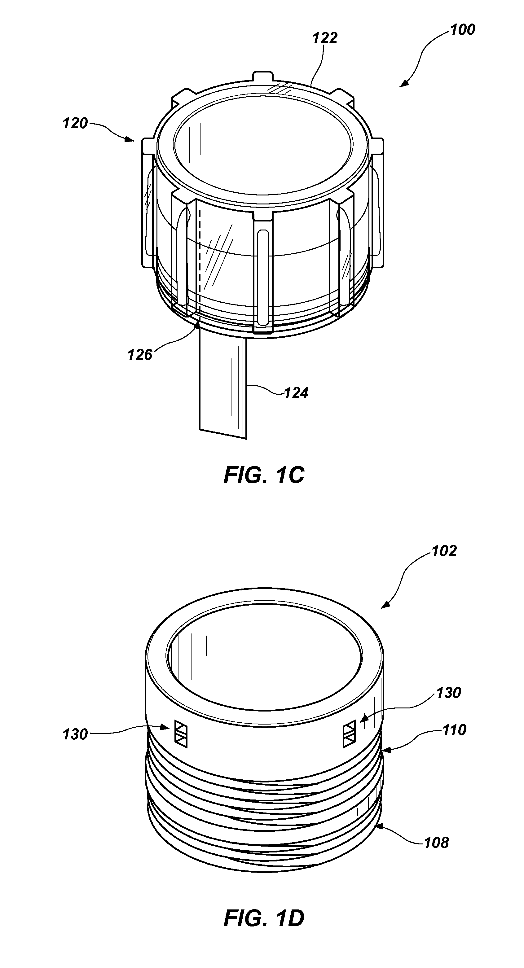
[0026]Referring to FIGS. 1A-1B a first embodiment of the cannula ring 100 is shown in a first state (FIG. 1A) and a second state (FIG. 1B). The cannula ring 100 includes a body portion 102 which may be formed of a substantially rigid material such as, for example, a metal, metal alloy, or any of a variety of biocompatible plastic materials. The body portion 102 may be formed generally as a tubular member having a substantially cylindrical wall 104 defining a lumen 106 or an opening passing through the body 102. The body portion 102 may include a number of features including a coupling structure 108 formed at one end of the body portion 102 that is configured to enable coupling with another device or structure such as, for example, a blood pump or a conduit. The coupling structure 108 may include, for example, a plurality of threads, a keyed twist-lock structure, a plurality of shoulders used in association with a ratchet structure, or it may be configured for connection with a compr...


PUM


Abstract

Cannula devices and related methods are provided. In accordance with one embodiment, a cannula ring includes a body portion having a substantially cylindrical member defining an opening therethrough. A plurality of anchor arms coupled with the body portion and configured to be positioned in a first, collapsed state and a second, deployed state, wherein the anchor arms each include a free end that is radially displaced from the body portion while in the second, deployed state relative to their positions while in the first, collapsed state. Suture rings and other associated structures and devices are also described.

Description

CROSS-REFERENCE TO RELATED APPLICATIONS[0001]This application claims the benefit of U.S. Provisional Patent Application 61 / 567,973, entitled CANNULA RING AND RELATED SYSTEMS AND METHODS, filed on Dec. 7, 2011, the disclosure of which is incorporated by reference herein, in its entirety.TECHNICAL FIELD[0002]Exemplary embodiments relate to a device for coupling a conduit to a vessel of the human body, and, more particularly to a cannula ring that enables attachment of various devices or structure with a chamber of the heart or other vessel.BACKGROUND[0003]Mechanical circulatory devices (MCDs) such as artificial hearts, ventricular assist devices (VADs) and other blood circulating systems and components have become increasingly recognized as life saving devices for patients whose hearts are diseased or have been injured by trauma, heart attack or other causes. VADs in particular, are recognized as a major life saving modality for assisting patients who suffer from congestive heart fail...

Claims


Application Information

Patent Timeline
Patent Type & Authority Applications(United States)
IPC IPC(8): A61M25/04A61M1/10A61M60/17A61M60/857
CPCA61M1/10A61M25/04A61B17/3421A61B17/3423A61B17/3462A61B17/3498A61M1/1008A61B2017/00871A61B2017/3425A61B2017/347A61B2017/3484A61B2017/3488A61B2017/00867A61M60/857A61M60/17A61M39/06A61M1/36
Inventor STANFIELD, RYANWOODARD, JOHNBEARNSON, GILL
Owner WORLD HEART
Why Eureka
Try Eureka