Magnetic field measuring apparatus and cell array
- Summary
- Abstract
- Description
- Claims
- Application Information
AI Technical Summary
Benefits of technology
Problems solved by technology
Method used
Image

Examples
example 1
(1) Modified Example 1
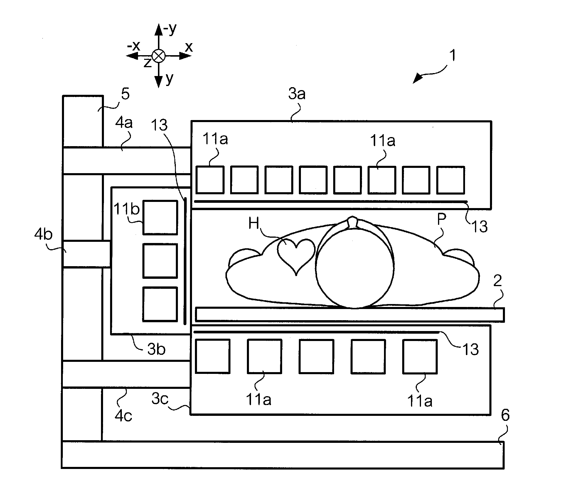
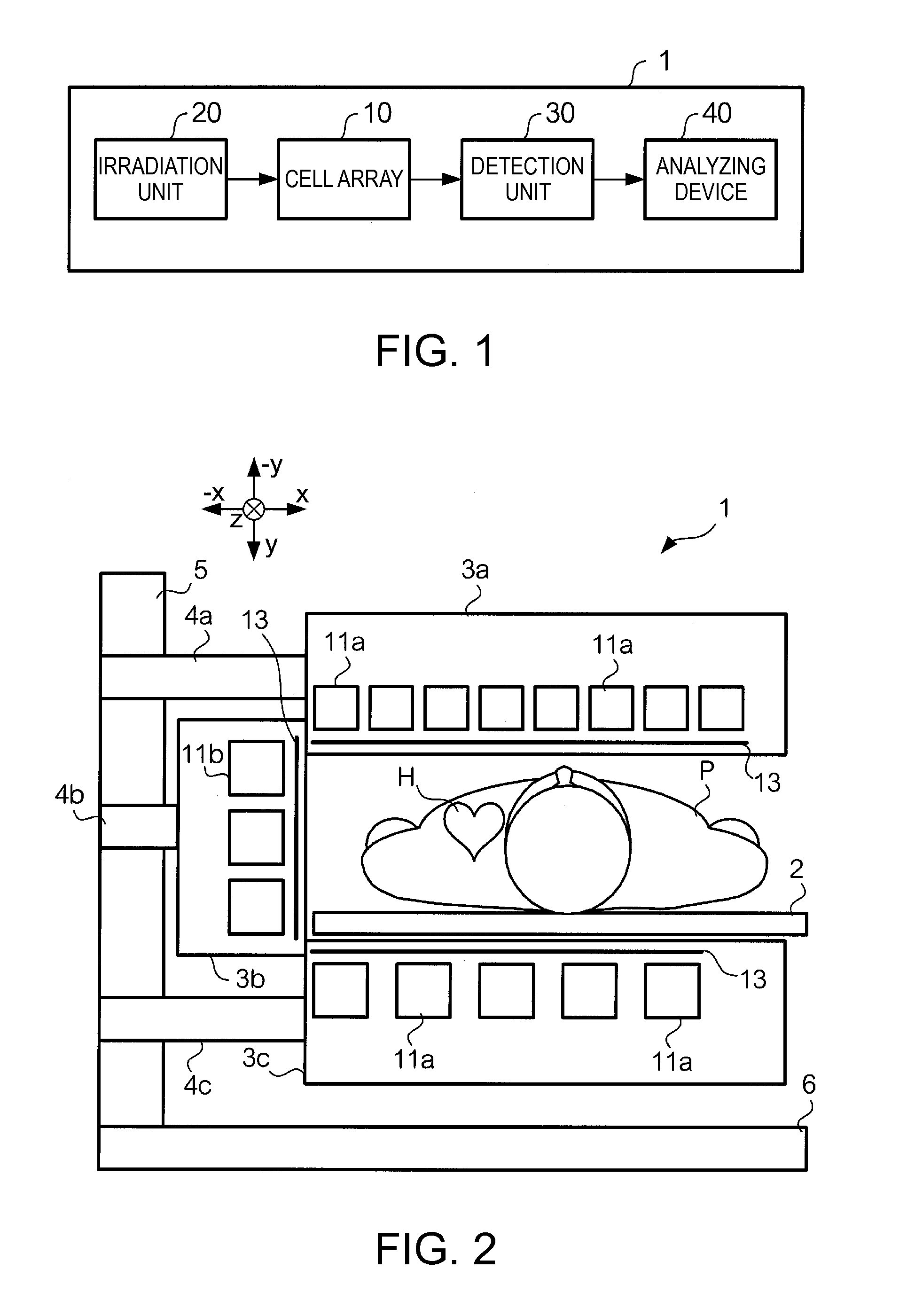
[0054]In the foregoing embodiment, although only the second cells 11b are arranged on the left side surface side and the back surface side of the subject P, the first cells 11a may be arranged also on the left side surface side or the back surface side. In this case, the first cells 11a may be arranged in an area close to the heart H of the subject P, and the second cells 11b may be arranged in an area far from the heart H. The area close the heart H is an area within a specified range from the heart H, and the area far from the heart H is the other area.
[0055]FIG. 10 is a view showing an example of arrangement of cells 11 in a magnetic field measuring apparatus 1A of this modified example. In this example of FIG. 10, the first cells 11a and the second cells 11b are arranged on the left side surface side of the subject P. The first cells 11a are arranged at the center portion close to the heart H of the subject P. On the other hand, the second cells 11b are arr...
example 2
(2) Modified Example 2
[0056]In the foregoing embodiment, although only the first cells 11a are arranged on the front surface side of the subject P, and only the second cells 11b are arranged on the side surface side and the back surface side, cells 11 different in size may be mixedly arranged. In this case, the first cells 11a may be arranged in an area close to the heart H of the subject P, and the second cells 11b may be arranged in an area far from the heart H. The area close to the heart H is an area within a specified range from the heart H, and the area far from the heart H is the other area.
[0057]FIG. 11 is a view showing an example of arrangement of cells 11 of this modified example. In FIG. 11, the cells 11 arranged on the front surface side of the subject P are shown. The first cells 11a and the second cells 11b are arranged on the front surface side of the subject P. The first cells 11a are arranged at the center portion close to the heart H of the subject P. On the other...
example 3
(3) Modified Example 3
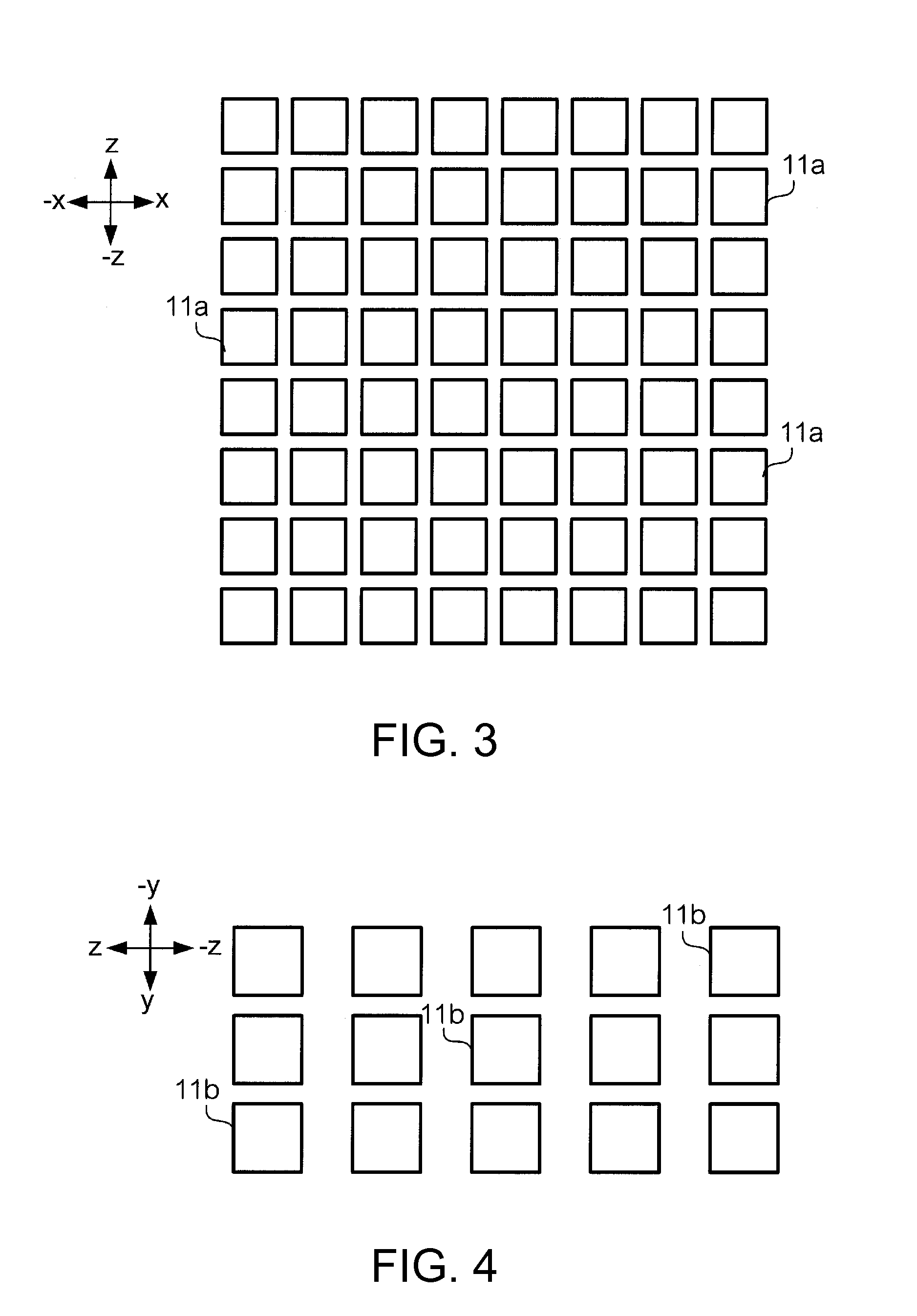
[0058]In the foregoing embodiment, although the plural cells 11 are two-dimensionally arranged in the matrix on the front surface side, the left side surface side and the back surface side of the subject P, the arrangement of the plural cells 11 is not limited to this.
[0059]FIG. 12 is a view showing an example of arrangement of cells 11 of a magnetic field measuring apparatus 1B of this modified example. The side surface of the subject P has a rounded shape. Then, in the example of FIG. 12, the cells 11 on the left side surface side of the subject P are arranged to coincide with the roundness of the body of the subject P. Incidentally, in this case, instead of the housings 3a, 3b and 3c shown in FIG. 2, a housing 3 containing all the cells 11 included in the cell array 10 may be provided. As stated above, the cells 11 may be arranged along the shape of the body of the subject P. By this, the distance between the heart H and the cell 11 can be reduced. As a resu...
PUM
 Abstract
Description
Claims
Application Information
 - R&D
- Intellectual Property
- Life Sciences
- Materials
- Tech Scout
- Unparalleled Data Quality
- Higher Quality Content
- 60% Fewer Hallucinations
Browse by: Latest US Patents, China's latest patents, Technical Efficacy Thesaurus, Application Domain, Technology Topic, Popular Technical Reports.
© 2025 PatSnap. All rights reserved.Legal|Privacy policy|Modern Slavery Act Transparency Statement|Sitemap|About US| Contact US: help@patsnap.com