Auto-Injector

a technology of auto-injector and injection needle, which is applied in the direction of automatic syringe, intravenous device, injection needle, etc., can solve the problems of user delivery an underdose, high injection force for users, and high risk of users, so as to achieve reliable removal

Active Publication Date: 2013-06-13
SANOFI AVENTIS DEUT GMBH
View PDF5 Cites 33 Cited by
  • Summary
  • Abstract
  • Description
  • Claims
  • Application Information

AI Technical Summary

Benefits of technology

[0040]Preferably a cap is provided at the proximal end of the housing. A sheet metal clip is attached to the cap for joint axial movement and independent rotation. The sheet metal clip is arranged to extend through an orifice into the housing when the cap is attached to the housing. The sheet metal clip comprises at least two barbs snapped into a circumferential notch or behind a shoulder of the protective needle shield. This

Problems solved by technology

Administering an injection is a process which presents a number of risks and challenges for users and healthcare professionals, both mental and physical.
There are numerous disadvantages to the user from this approach.
This means that the user can deliver an underdose if the device is not used properly (i.e. the plunger is not fully pressed to its end position).
Injection forces ma

Method used


Image

  • Auto-Injector
  • Auto-Injector
  • Auto-Injector

Examples


Embodiment Construction

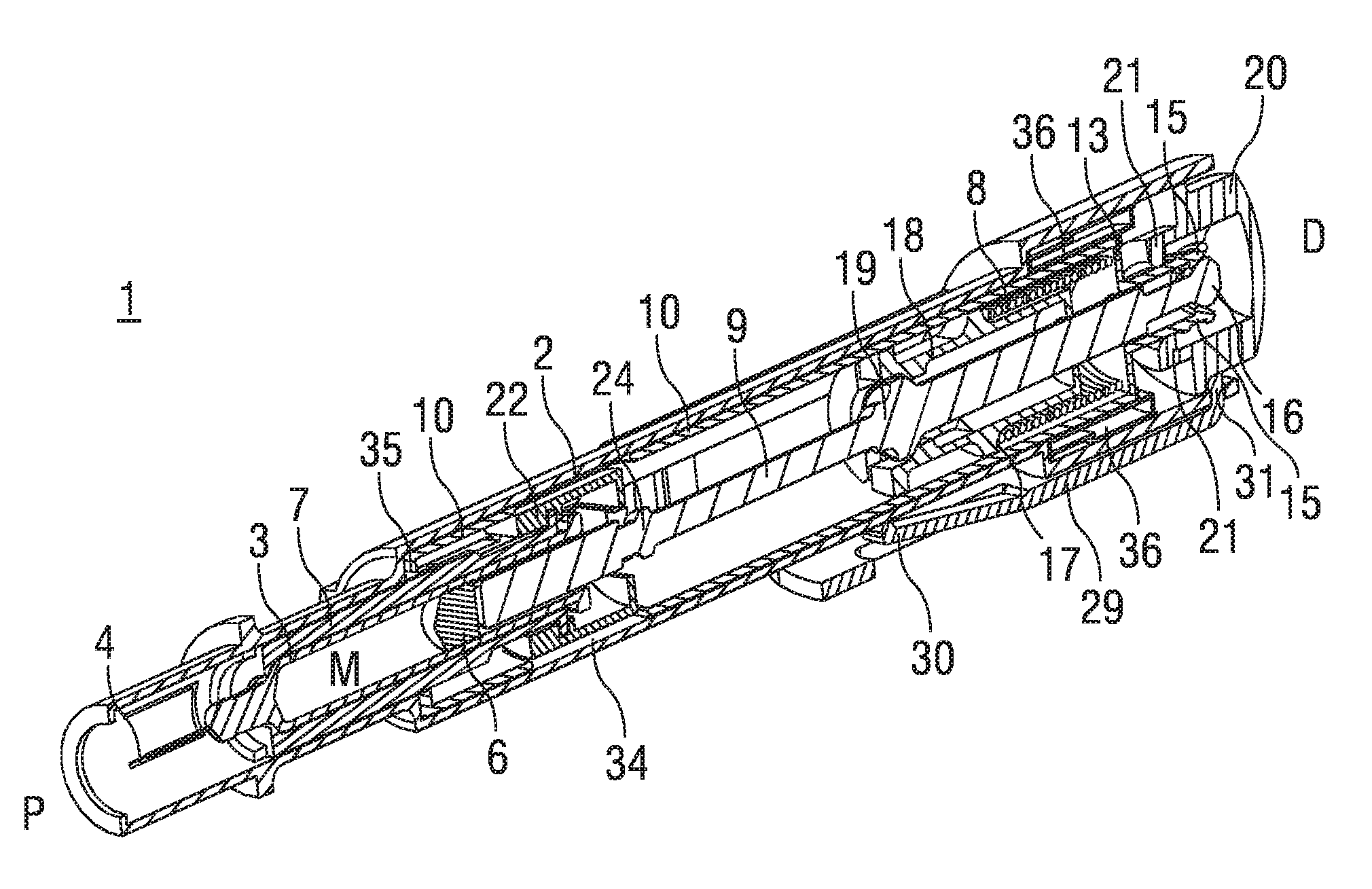
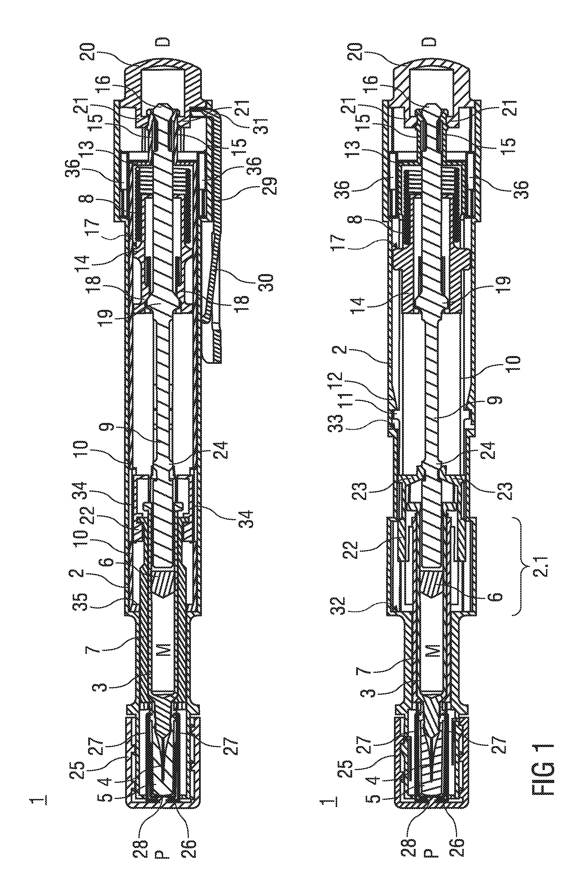
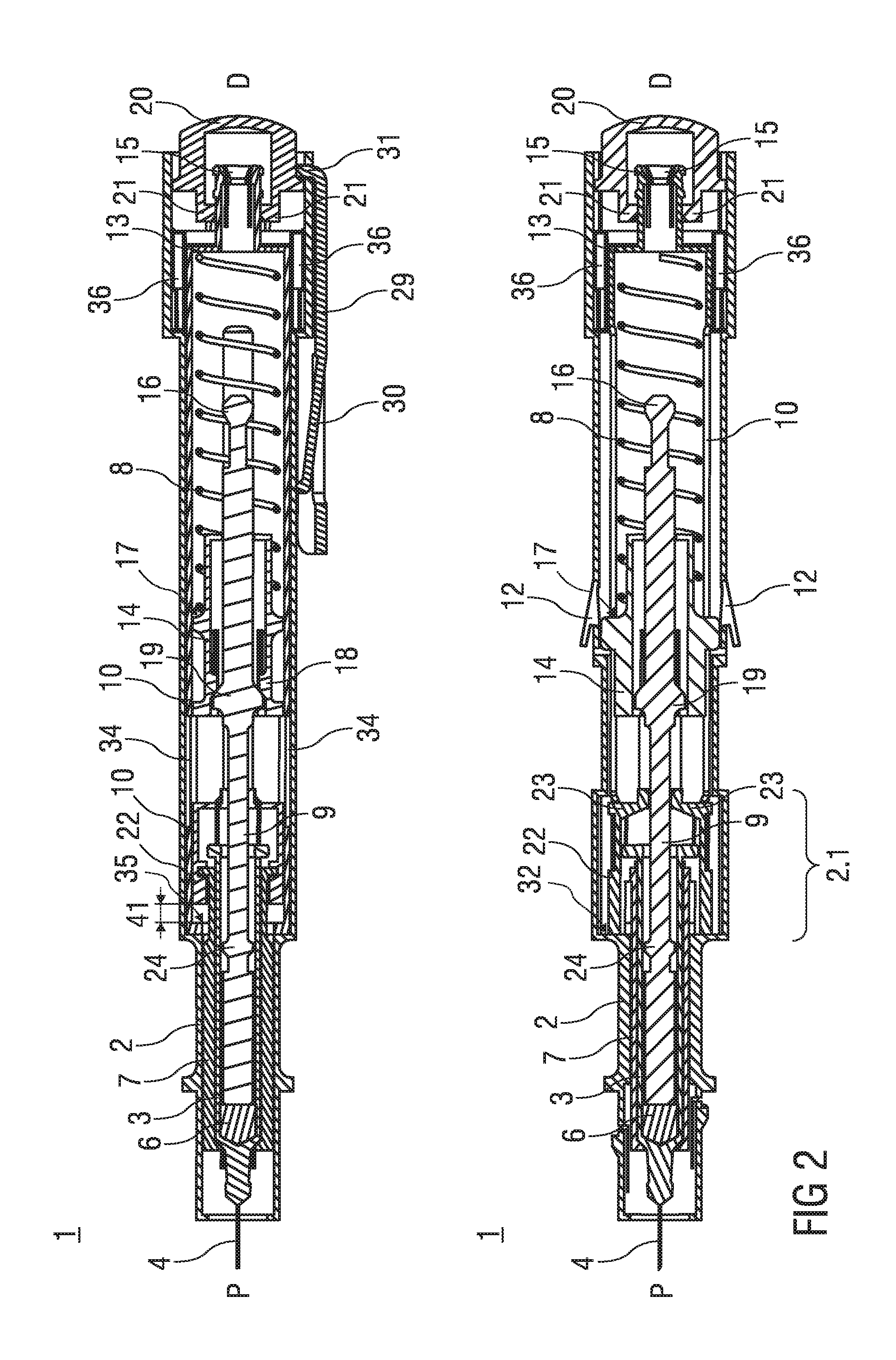
[0118]FIG. 1 shows two longitudinal sections in different section planes of an auto-injector 1, the different section planes approximately 90° rotated to each other. The auto-injector 1 comprises an elongate housing 2. A syringe 3, e.g. a Hypak syringe, with a hollow needle 4 is arranged in a proximal part of the auto-injector 1. When the auto-injector 1 or the syringe 3 is assembled a protective needle shield 5 is attached to the needle 4. A stopper 6 is arranged for sealing the syringe 3 distally and for displacing a liquid medicament M through the hollow needle 4. The syringe 3 is held in a tubular syringe carrier 7 and supported at its proximal end therein. A single compression spring 8 is arranged in a distal part of the auto-injector 1. A plunger 9 is arranged for forwarding the spring force of the compression spring 8.

[0119]Inside the housing 2 a retraction sleeve 10 is slidably arranged. Before the injection is triggered as shown in FIG. 1 the retraction sleeve 10 is in a ma...


PUM


Abstract

The invention relates to an auto-injector (1) for administering a dose of a liquid medicament (M), comprising:
    • an elongate housing (2) arranged to contain a syringe (3) with a hollow needle (4) and a stopper (6) for sealing the syringe (3) and displacing the medicament (M), the housing (2) having a distal end (D) and a proximal end (P) with an orifice intended to be applied against an injection site, wherein the syringe (3) is slidably arranged with respect to the housing (2),
    • spring means (8) capable of, upon activation:
      • pushing the needle (4) from a covered position inside the housing (2) into an advanced position through the orifice and past the proximal end (P),
      • operating the syringe (3) to supply the dose of medicament (M), and
      • retracting the syringe (3) with the needle (4) into the covered position after delivering the medicament (M),
    • activating means (20) arranged to lock the spring means (8) in a pressurized state prior to manual operation and capable of, upon manual operation, releasing the spring means (8) for injection. The spring means (8) is a single compression spring (8) arranged to be grounded at a distal end (8.1) in the housing (2) for advancing the needle (4) and for injecting the dose of medicament (M) via a plunger (9) and wherein the compression spring (8) is arranged to have its ground in the housing (2) switched to its proximal end (8.2) for retracting the syringe (3).

Description

TECHNICAL FIELD[0001]The invention relates to an auto-injector for administering a dose of a liquid medicament according to the preamble of claim 1.BACKGROUND OF THE INVENTION[0002]Administering an injection is a process which presents a number of risks and challenges for users and healthcare professionals, both mental and physical.[0003]Injection devices (i.e. devices capable of delivering medicaments from a medication container) typically fall into two categories—manual devices and auto-injectors.[0004]In a manual device—the user must provide the mechanical energy to drive the fluid through the needle. This is typically done by some form of button / plunger that has to be continuously pressed by the user during the injection. There are numerous disadvantages to the user from this approach. If the user stops pressing the button / plunger then the injection will also stop. This means that the user can deliver an underdose if the device is not used properly (i.e. the plunger is not fully...

Claims


Application Information

Patent Timeline
IPC IPC(8): A61M5/32
CPCA61M5/2033A61M5/3204A61M5/3232A61M2005/206A61M2005/2073A61M5/326A61M5/3202
Inventor EKMAN, MATTHEWBARROW-WILLIAMS, TIMOTHY DONALDHOURMAND, YANNICK
Owner SANOFI AVENTIS DEUT GMBH
Why Eureka
Try Eureka