Module feeder system and method to use same

a feeder system and module technology, applied in the field of module feeder system and method, can solve the problems of high cost and massive amount of additional machinery

Inactive Publication Date: 2013-06-20
BROWN JOE GOODWIN
View PDF2 Cites 5 Cited by
  • Summary
  • Abstract
  • Description
  • Claims
  • Application Information

AI Technical Summary

Problems solved by technology

Such additional machinery is expensive and massive requiring a sub...

Method used


Image

  • Module feeder system and method to use same
  • Module feeder system and method to use same
  • Module feeder system and method to use same

Examples


Embodiment Construction

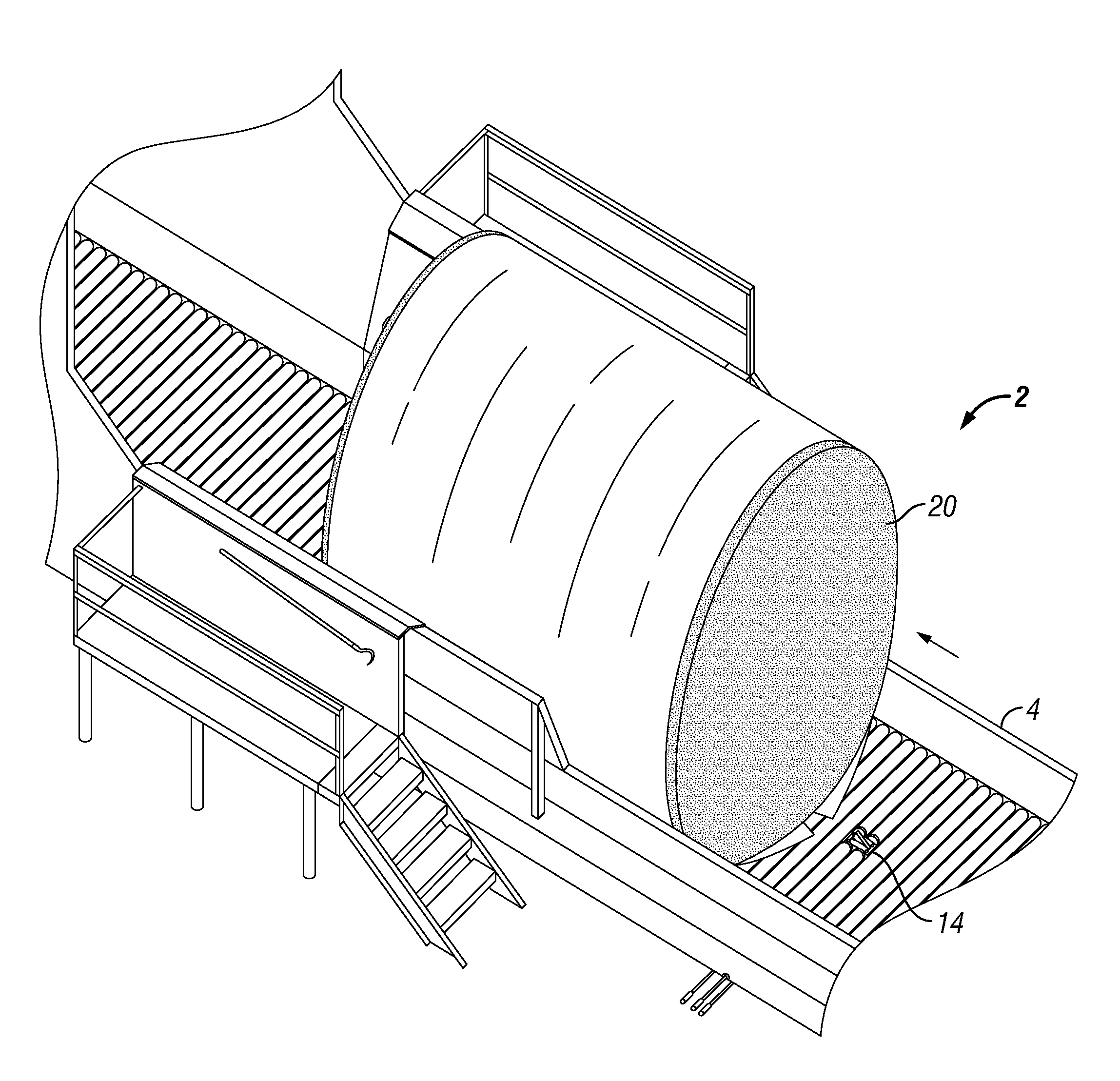
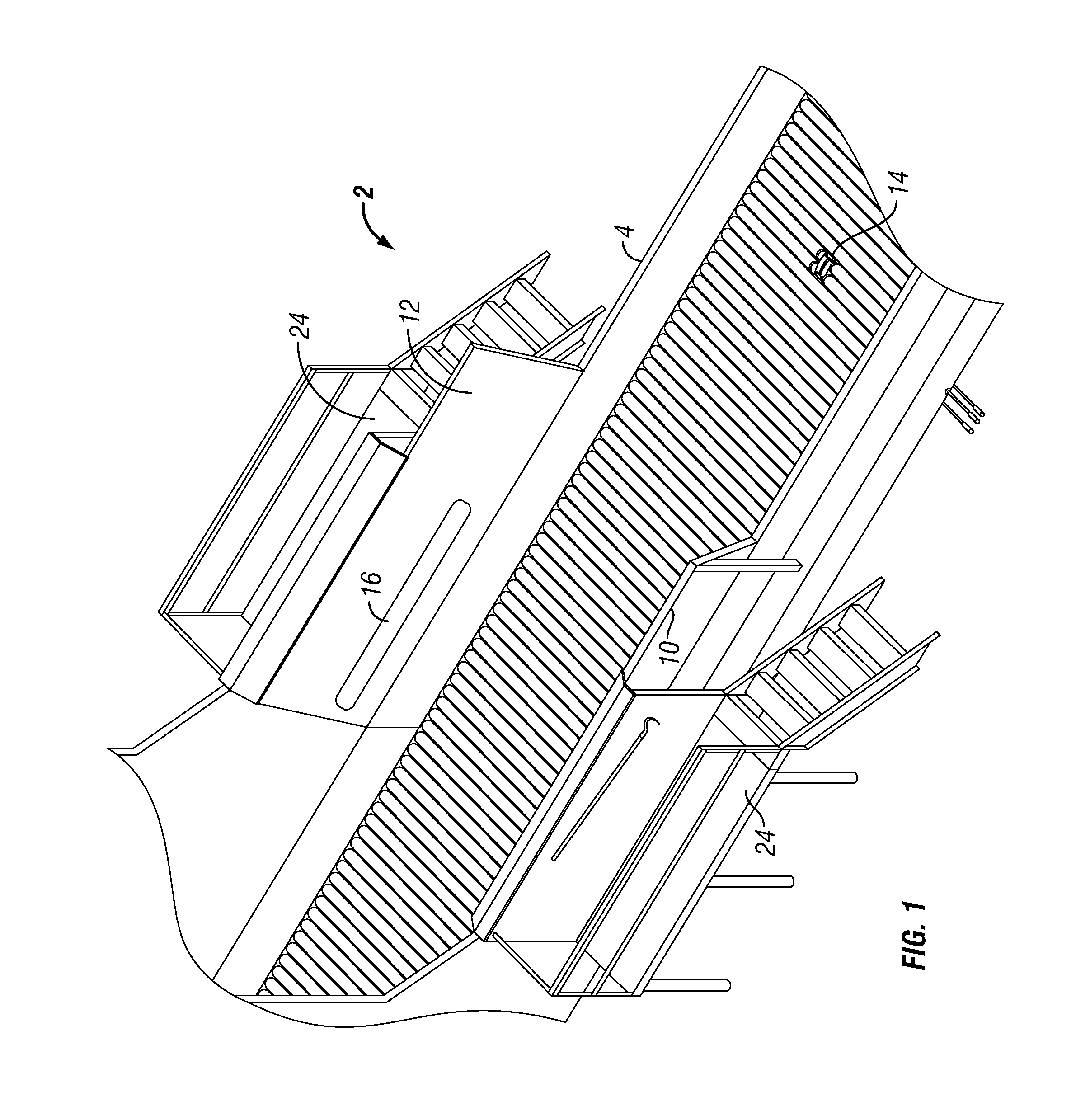
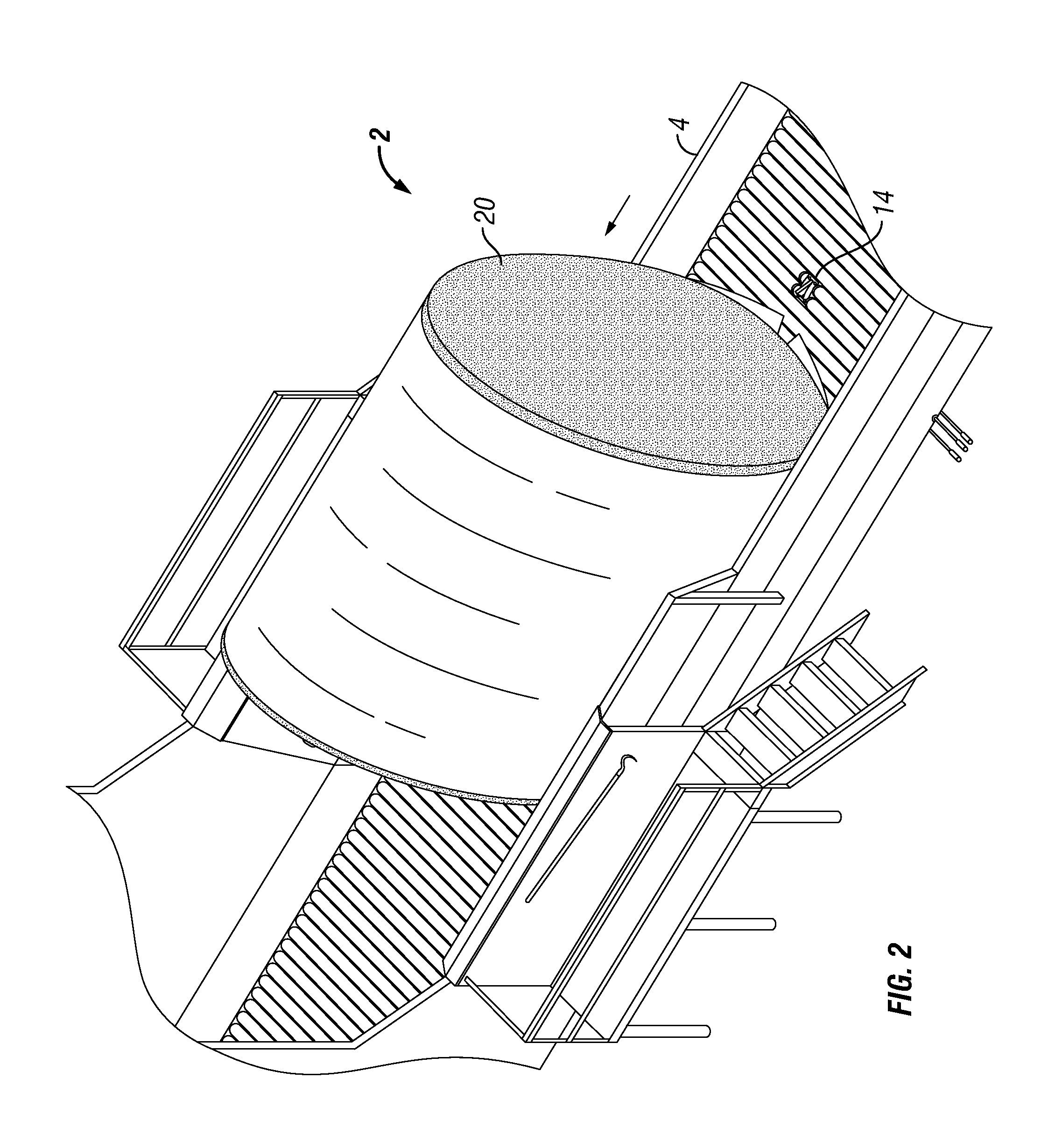
[0018]Referring to FIGS. 1 to 2, a module feeder system 2 is disclosed. Module feeder system comprises a module feeder 4, a cutting device 14 and at least one hydraulic cylinder 16. In one embodiment, module feeder 4 comprises an unload bed 6, a feeder bed8, a first side wall 10 and a second side wall 12. Module feeders typically consist of three sections of beds which include an unload, stage, and feed bed. The beds are used to move cotton modules into the gin. Module feeders typically comprise two and a half beds. The number of beds used on a module feeder may vary as desired by one skilled in the art. Unload bed 6 is typically 40 feet in length. A cotton module 20 is unloaded onto unload bed 6. Upon activation, module feeder 4 will move a cotton module 20 from the unload bed 6 to feeder bed 8. In one embodiment, module feeder 4 comprises a first side wall 10 and a second side wall 12. First side wall 10 and second side wall 12 are contiguous to feeder bed 8. First side wall 10 an...


PUM


Abstract

A module feeder system is disclosed. The module feeder system comprises a module feeder which has an unload bed, a feeder bed, a first side wall and a second side wall. A cutting device is attached to the feeder bed. At least one hydraulic cylinder is positioned on each of the first and second side walls. Each hydraulic cylinder is configured to project in a direction away from the sidewalls and over the feeder bed. A method used to unwrap a cotton module is also disclosed.

Description

FIELD[0001]The present disclosure relates generally to a module feeder system and method to use the same. More specifically, the present disclosure relates to a module feeder system and method to unwrap round cotton modules as the seed cotton is conveyed and fed into the cotton gin.BACKGROUND[0002]In modern cotton production, seed cotton commonly arrives at a cotton gin in compressed modules which are wrapped in plastic. Cotton modules are built on the cotton field by a cotton module builder, a machine used in the harvest and processing of cotton. The module builder allows cotton to be harvested quickly and compressed into large modules which are subsequently tarped and temporarily stored at the edge of a cotton field until they are loaded on trucks and carried to a cotton gin for processing. When the cotton modules arrive at the cotton gin, they are placed on cotton module feeders which are designed to move cotton from delivery to the cotton gin. Cotton module feeders break up or d...

Claims


Application Information

Patent Timeline
IPC IPC(8): B65B69/00D01B1/04
CPCB65B69/005B65B69/0033
Inventor BROWN, JOE GOODWIN
Owner BROWN JOE GOODWIN
Why Eureka
Try Eureka