
Non-Bearing Modular Construction System

a technology of modular building and construction system, which is applied in the field of modular building construction system, can solve the problems of labor rate increase, inflated construction cost of high-rise buildings, and reduced production efficiency

Active Publication Date: 2013-06-20
PREFORM SYST
View PDF26 Cites 37 Cited by
  • Summary
  • Abstract
  • Description
  • Claims
  • Application Information

AI Technical Summary

Benefits of technology

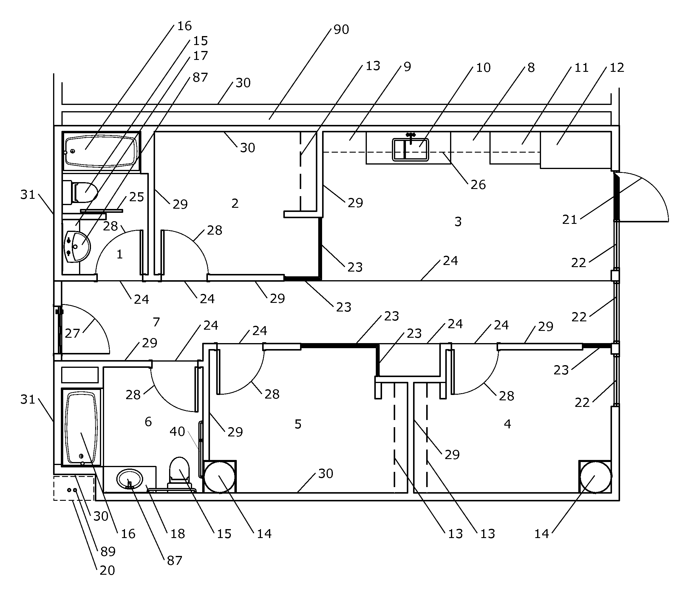
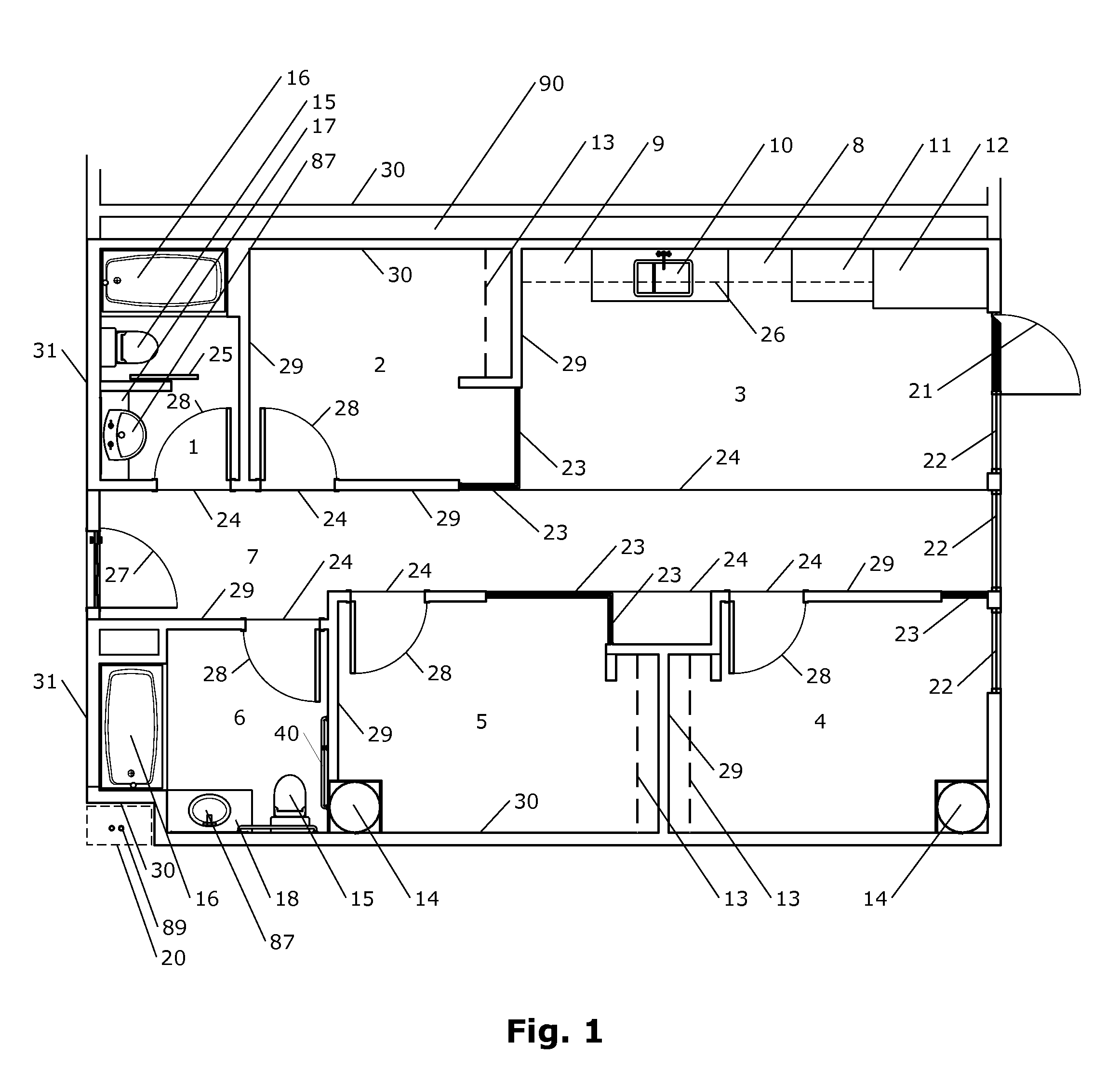
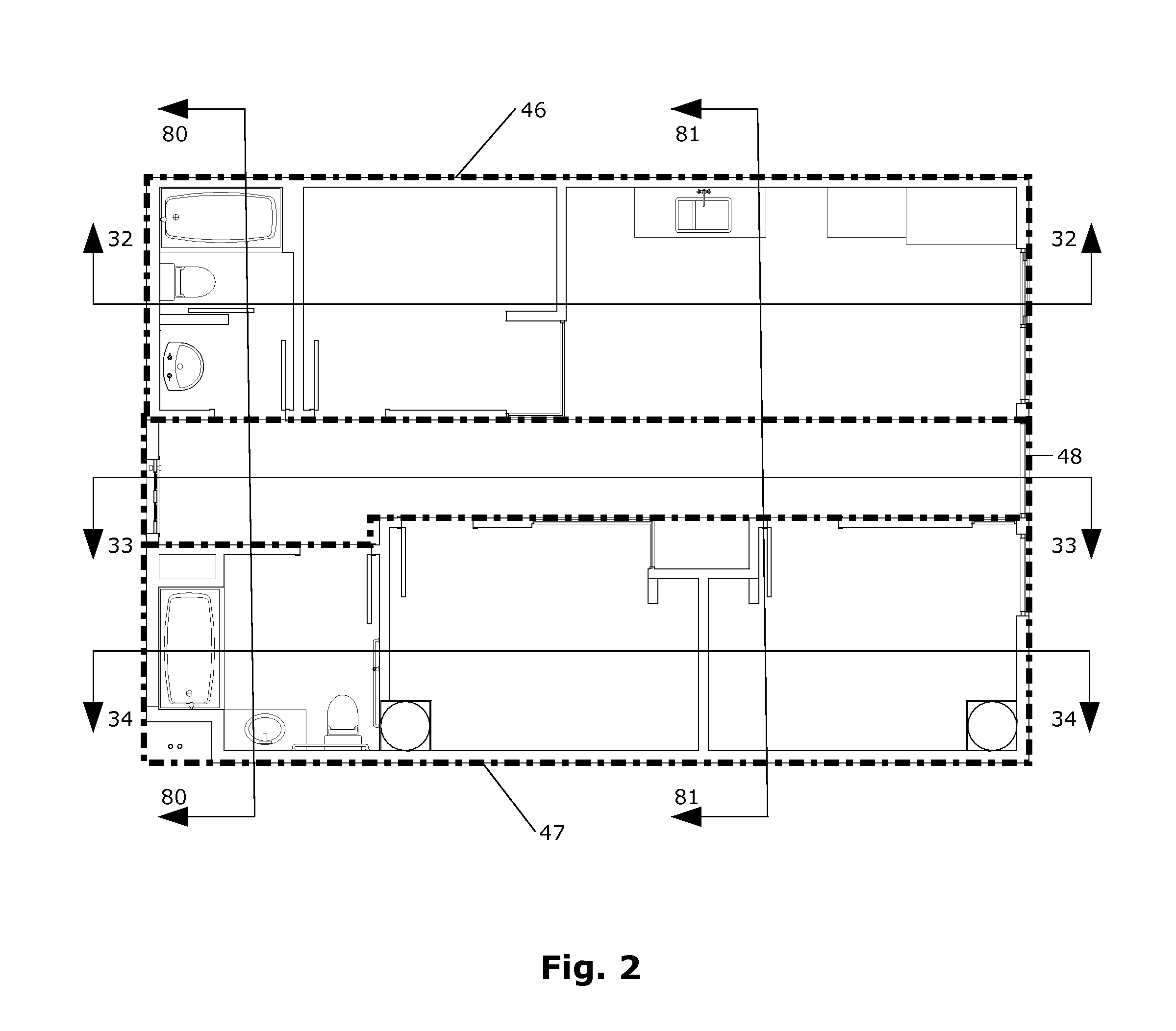
The patent describes a building system made up of prefabricated units with vertically disposed formwork structures and a horizontal deck made of structural bearing material. The prefabricated units are lowered onto a base and the formwork structures are filled with structural bearing material to create vertically disposed structural elements. A single structural deck is then applied to the horizontal upper exterior surfaces of the prefabricated units. The technical effects of this design include improved efficiency and speed of construction, as well as more stable and secure buildings.

Problems solved by technology

The typical cost of construction for high rise buildings is inflated by the cost of onsite labor, particularly when onsite labor intensive tasks are performed higher and higher above ground level.
As construction activities move up a tall building, labor rates increase and production becomes less efficient for a number of reasons including the necessity of moving project materials by crane or elevator to get the materials to their final installation location.
At higher elevations, movement of both materials and labor slows down, increasing construction schedule times and again adding to the construction cost.
As areas urbanize higher density and increased land cost make high-rise buildings a necessity.
Unfortunately in many economic climates high rise building has become unfeasible due to the high cost of this building type.

Method used


Image

  • Non-Bearing Modular Construction System
  • Non-Bearing Modular Construction System
  • Non-Bearing Modular Construction System

Examples


Embodiment Construction

[0023]In the following description, for purposes of description and not limitation, details and descriptions are set forth in order to provide a thorough understanding of the disclosed embodiments. However, it will be apparent to those skilled in the art that the present invention may be practiced in other embodiments that depart from these details and descriptions.

[0024]Additionally, in the subject description, the word “exemplary” is used to mean serving as an example, instance, or illustration. Any embodiment or design described herein as “exemplary” is not necessarily to be construed as preferred or advantageous over other embodiments or designs. Rather, use of the word exemplary is intended to present concepts in a concrete manner.

[0025]Prior modular construction systems are often flawed in that they rely too heavily on complicated and largely unproven structural systems rather than integrating with conventional construction, which generally results in too rigid a system that c...


PUM


Abstract

Methods and apparatus facilitate the construction of a building using prefabricated building units, each having a horizontal upper exterior surface and a plurality of vertical wall surfaces, wherein at least some of the prefabricated building units have at least one hollow column formwork structure. The prefabricated building units are lowered onto a pre-existing base at a construction site. A first story of the building is created by arranging a plurality of the prefabricated building units adjacent to each other on the base. Structural bearing material is applied to fill the hollow column formwork structures to create structural columns connected to the structural deck. Structural bearing material is applied to the horizontal upper exterior surfaces of the adjacent prefabricated building units to create a single structural deck over the prefabricated building units.

Description

RELATED APPLICATIONS[0001]This application claims priority from U.S. provisional patent application No. 61,561,750 filed on Nov. 18, 2011, which is incorporated herein by reference in its entirety for all purposes.FIELD OF INVENTION[0002]The present invention generally relates to the field of modular building construction systems. More particularly, the disclosed embodiments relate to a system and method of assembly for prefabricated modular building units used in combination with traditional methods and materials of construction to construct noncombustible buildings of any possible height up to the limits imposed by building codes, including high-rise buildings.BACKGROUND[0003]The typical cost of construction for high rise buildings is inflated by the cost of onsite labor, particularly when onsite labor intensive tasks are performed higher and higher above ground level. As construction activities move up a tall building, labor rates increase and production becomes less efficient fo...

Claims


Application Information

Patent Timeline
IPC IPC(8): E04B1/348
CPCE04B1/348E04B1/34869E04B1/165E04B1/16E04B1/34807E04B1/20E04B1/35E04H1/005E04B2103/02
Inventor AUSTIN, DOUGLASJENCKS, WILLIAM
Owner PREFORM SYST
Learn More