Fan unit for a heat exchanger

Active Publication Date: 2013-06-20
JOHNSON ELECTRIC INTERNATIONAL AG
View PDF5 Cites 1 Cited by
  • Summary
  • Abstract
  • Description
  • Claims
  • Application Information

AI Technical Summary

Benefits of technology

The present invention provides a fan unit for heat exchangers that includes a spray protection screen with an outwardly projecting deviating formation designed to deflect water that may flow over the screen during operation. The screen is fixed to the fan unit in a way that it is substantially vertical and defines at least one inlet opening for air cooling the electric motor. The outwardly projecting deviating formation prevents water from entering the fan unit and potentially causing damage. The fan unit can be used as a cooling fan module for vehicles and is particularly useful in engine compartments.

Problems solved by technology

This, of course, is undesirable.

Method used


Image

  • Fan unit for a heat exchanger
  • Fan unit for a heat exchanger
  • Fan unit for a heat exchanger

Examples


Embodiment Construction

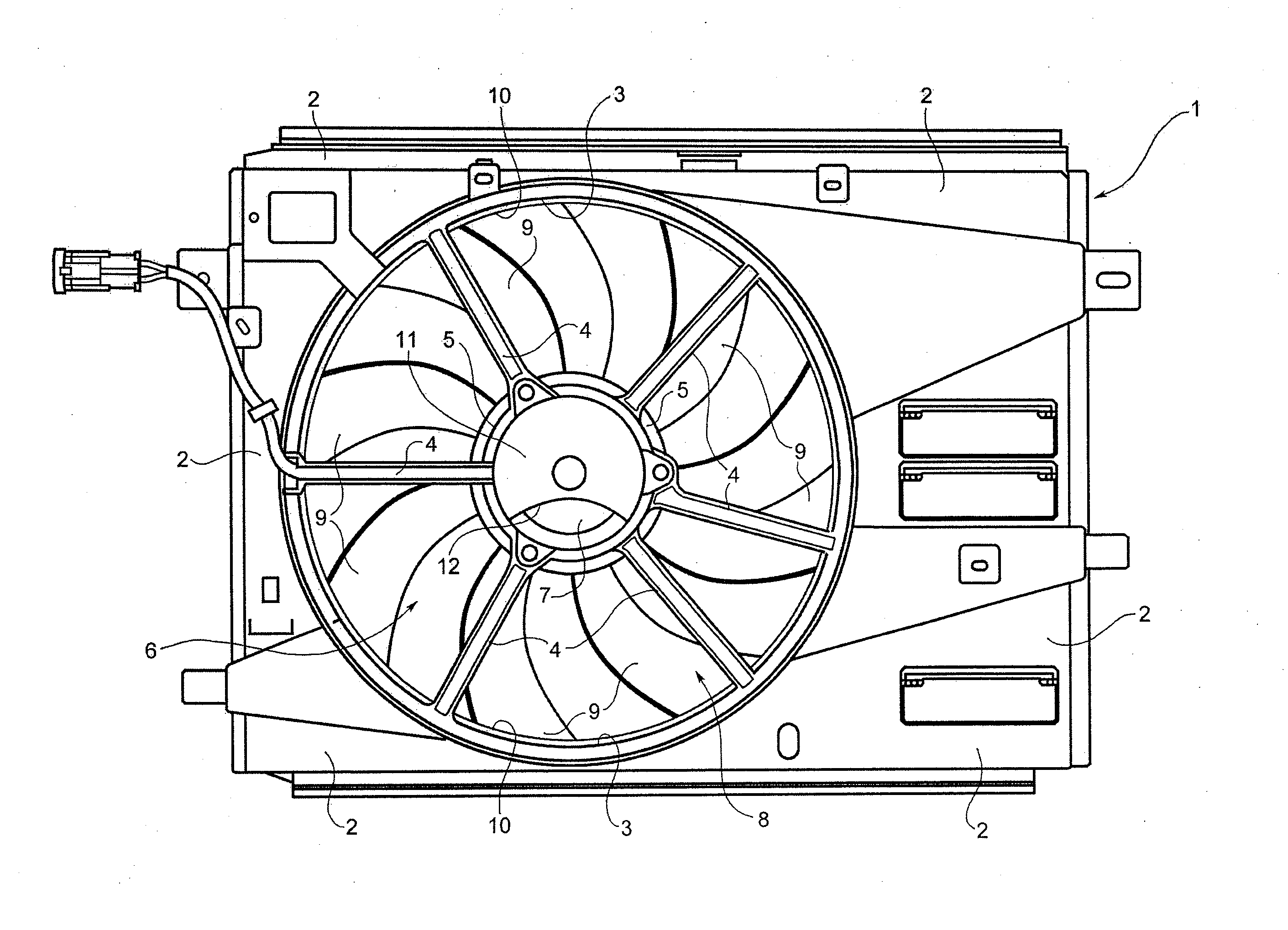
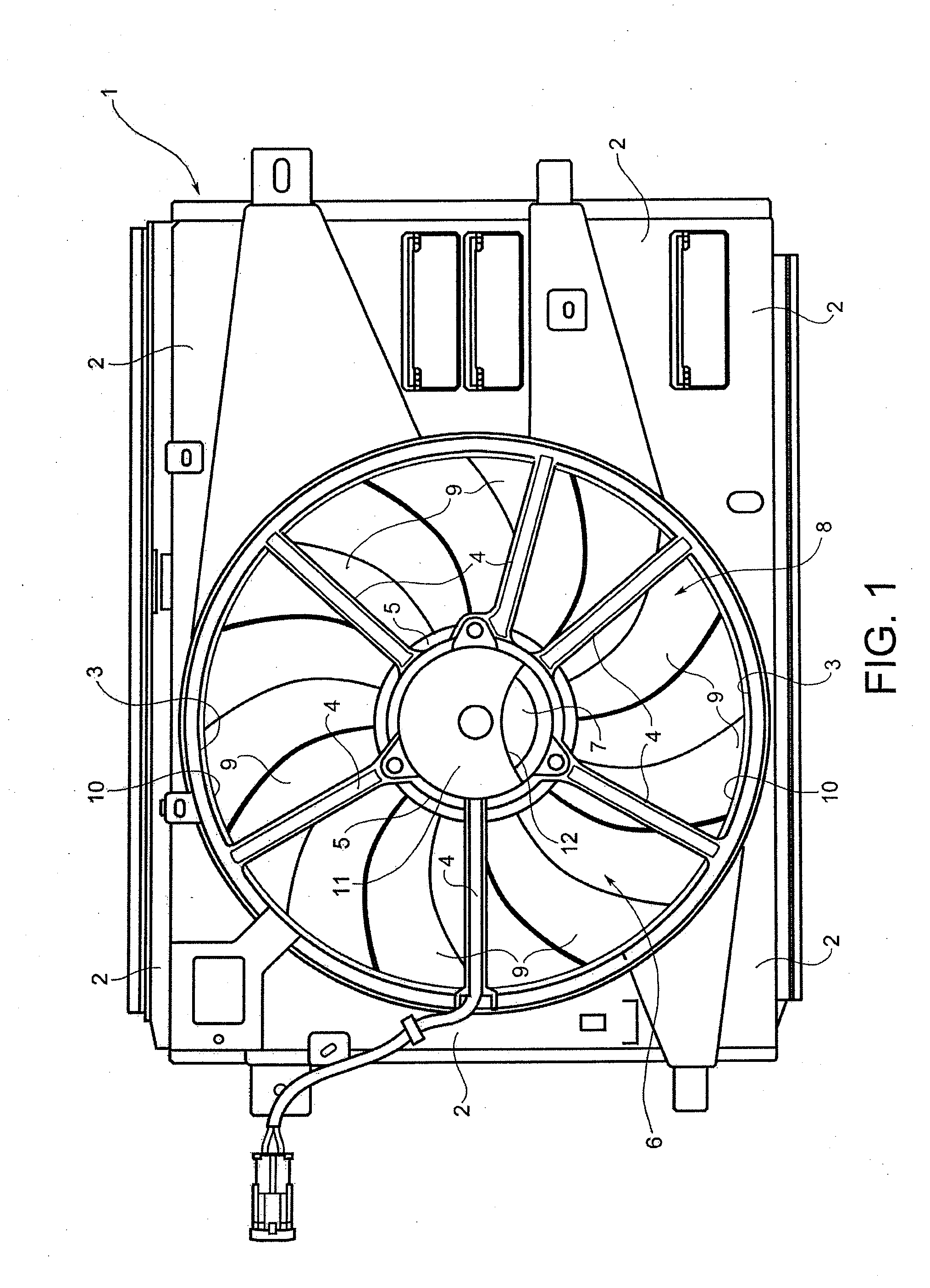
[0017]In FIGS. 1 and 2, reference number 1 denotes in its entirety a fan unit for a heat exchanger (not shown), such as a radiator of a motor vehicle. In a manner known per se, the fan unit 1 comprises a plate-like support structure, or shroud, 2, which is made of moulded plastic. The support structure or shroud 2 has a main opening 3 defining a passage for air to flow.

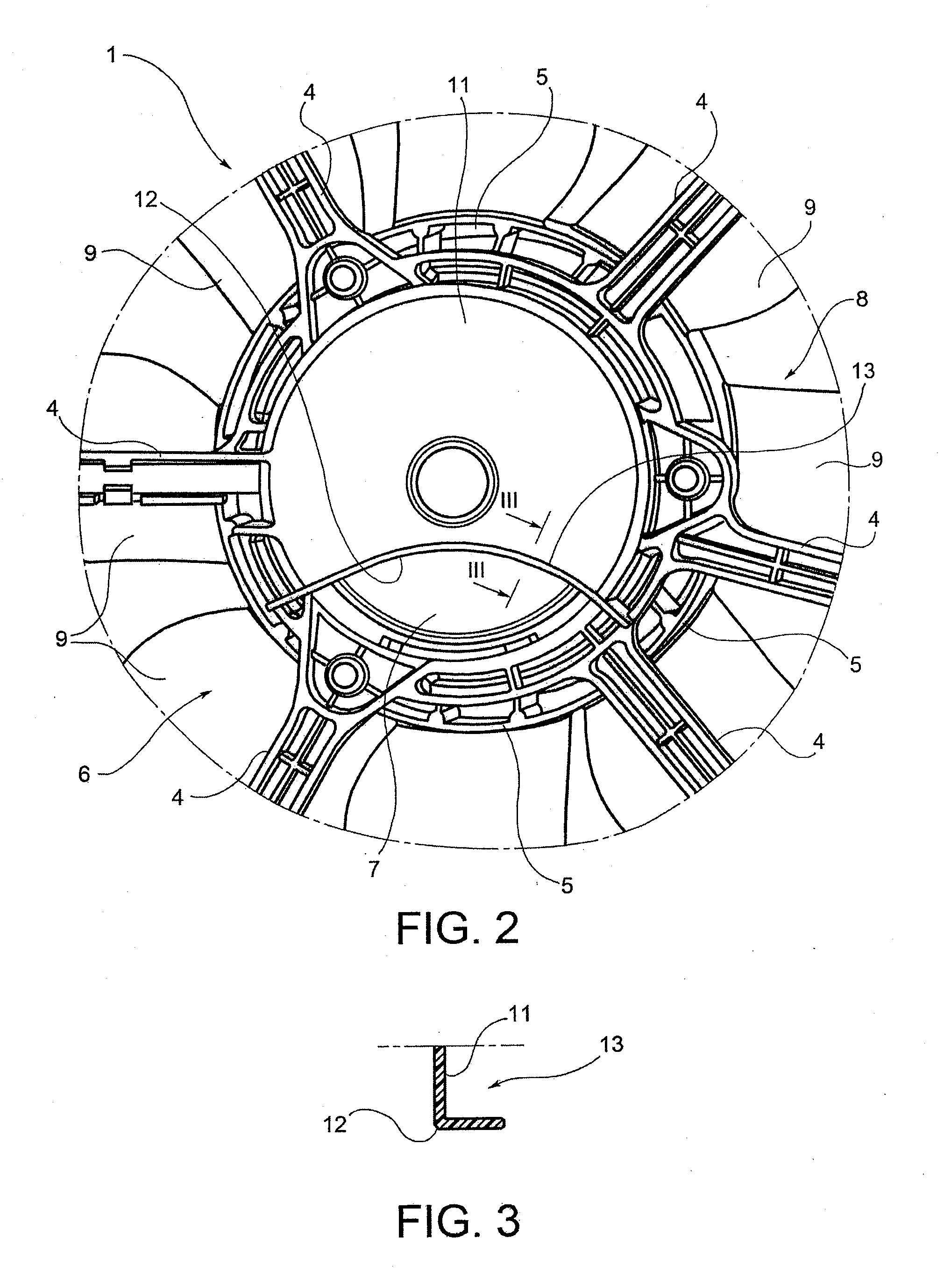
[0018]In the embodiment shown by way of example, a plurality of spokes 4 extend from the edge of the main opening 3 and are connected to a central annular support element 5. An electric fan, denoted overall by 6, is fixed to the annular support element 5. The fan 6 comprises an electric drive motor 7 which is fixed to the annular support element 5 and an impeller 8 having a plurality of shaped blades 9, the remote ends of which are connected to an outer ring 10 (FIG. 1).

[0019]A spray protection screen 11 is associated with the rear side of the motor 7, i.e. the side opposite to that of the impeller 8, being fixed to t...


PUM


Abstract

A fan unit for a heat exchanger, has a plate-like support structure or shroud with a main opening defining an air passage for ventilation of the heat exchanger. An electric drive motor is fixed to the support structure or shroud. An impeller is arranged inside the main opening and driven by the drive motor. A spray protection screen associated with a side of the motor remote from the impeller is fixed to the support structure or shroud in such a way that, during use, it is substantially vertical and defines an inlet opening for an air flow for cooling the motor. The spray protection screen has an outwardly projecting deviating formation designed to deflect outside of the inlet opening, water which may flow over the outer surface of the screen during operation of the fan unit.

Description

CROSS REFERENCE TO RELATED APPLICATIONS[0001]This non-provisional patent application claims priority under 35 U.S.C. §119(a) from Patent Application No. TO2011U000140 filed in Italy on Dec. 15, 2011.FIELD OF THE INVENTION[0002]This invention relates to a fan unit for a heat exchanger and in particular, to a fan unit for a heat exchanger of a radiator for a motor vehicle.BACKGROUND OF THE INVENTION[0003]More specifically the invention relates to a fan unit of the type comprising: a plate-like support structure or shroud which has a main opening defining a passage for an air flow for ventilation of the exchanger; and an electric fan including an electric drive motor fixed to the support structure or shroud in the region of the main opening, and an impeller with blades arranged inside the main opening and connected to the drive motor. A spray protection screen is associated with the side of the motor remote from the impeller and is fixed to the support structure in such a way that, dur...

Claims


Application Information

Patent Timeline
IPC IPC(8): F01P5/06
CPCF01P5/06F04D19/002F04D25/082F04D29/5806F01P5/02F01P11/10F04D29/54F01P11/00
Inventor SPERETTA, GIANNIDAL COLLE, DANIELE
Owner JOHNSON ELECTRIC INTERNATIONAL AG
Why Eureka
Try Eureka