Harvester for potatoes, beets and other root crops

a technology for potatoes and beets, applied in the field of harvesters for potatoes, beets and other root crops, can solve the problems that the damage of the harvested crop, in particular potatoes, cannot be excluded, and achieve the effect of optimal separation efficiency and efficient configuration

Active Publication Date: 2013-06-20
GRIMME LANDMASCHFAB
View PDF17 Cites 3 Cited by
  • Summary
  • Abstract
  • Description
  • Claims
  • Application Information

AI Technical Summary

Benefits of technology

[0009]The harvested mix that is dug up by the digging shares can have various consistencies, in accordance with the respective soil conditions, wherein the harvested crop, for example, can be in a mix that contains sandy and / or loamy structures. With the adjustability in accordance with the present invention of conveying slants in the area of the conveying stretch of the screen conveyor belt, it is possible to react quickly to the different soil conditions and to react at essentially any point in time of the harvesting process with different conveying slants to changing soil and / or moisture conditions of the soil. The screening effect of the system can be optimized by targeted adjustment of the incline angle of the conveying stretch or of the area of a respective screening zone in such a way that, while a gentle treatment of the harvested crop that is being moved permanently in an upward direction is ensured, an optimal separation of the crop from the soil structures in the area of the screening zones is realized at the same time.
[0012]The configuration according to the invention makes it possible that along the conveying stretch more than only two conveying stretch sections are provided that have changeable conveying slants, respectively. It has been found that the screen conveyor belt has optimal screening action when it is advantageously provided with changeable incline angles in the area of the conveying slants in a range between 0 degrees and 60 degrees, preferably between 15 degrees and 40 degrees. These incline angles can be of the same magnitude in the area of the conveying slants, respectively. It is provided that the sections of the conveying stretch are adjusted to different slant angles, respectively, so that in the conveying direction varying screening conditions are effective. These adjustments of the conveying slants can be individually performed in each conveying stretch section. Also, it is conceivable that a joint adjustment of all sections of the conveying stretch is realized, preferably simultaneously.
[0014]The guide elements are movable individually or together in such a way that, beginning at the leading return pulley that defines the start of the screening zone, the respective changes of the conveying slants are effected in the conveying stretch sections that can be defined by the guide elements. By arranging several guide elements arranged along the screening zone so as to be spaced apart from each other, it is conceivable to move them in groups. In this connection, a plurality of conveying stretch sections with different conveying slants can be formed along the conveying stretch in such a way that the harvested mix is moved on “steep” and “less steep” conveying stretch sections so that therefore screening phases of different intensity are effective.
[0021]Based on the afore described concept of the screen conveyor with changeable conveying slants, this basic solution can in principle also be applied to a screen system in harvesters in which the screening zone of the respective conveying stretch is formed by several screen conveyor belts that are arranged sequentially. An efficient configuration can be achieved in that at least the screen conveyor belt that adjoins immediately the digging shares is provided with a support and adjusting construction which enables the adjustment of different conveying slants. Also, it is conceivable to adjust the sequentially arranged screen conveyor belts individually or jointly to appropriate conveying slants with optimal separation efficiencies.

Problems solved by technology

These drop stages that are adjustable with respect to the step height generate a relative movement of the parts of the harvested mix so that separation of soil from the crop is improved but, at the same time, damage of the harvested crop, in particular potatoes, cannot be excluded.

Method used


Image

  • Harvester for potatoes, beets and other root crops
  • Harvester for potatoes, beets and other root crops
  • Harvester for potatoes, beets and other root crops

Examples


first embodiment

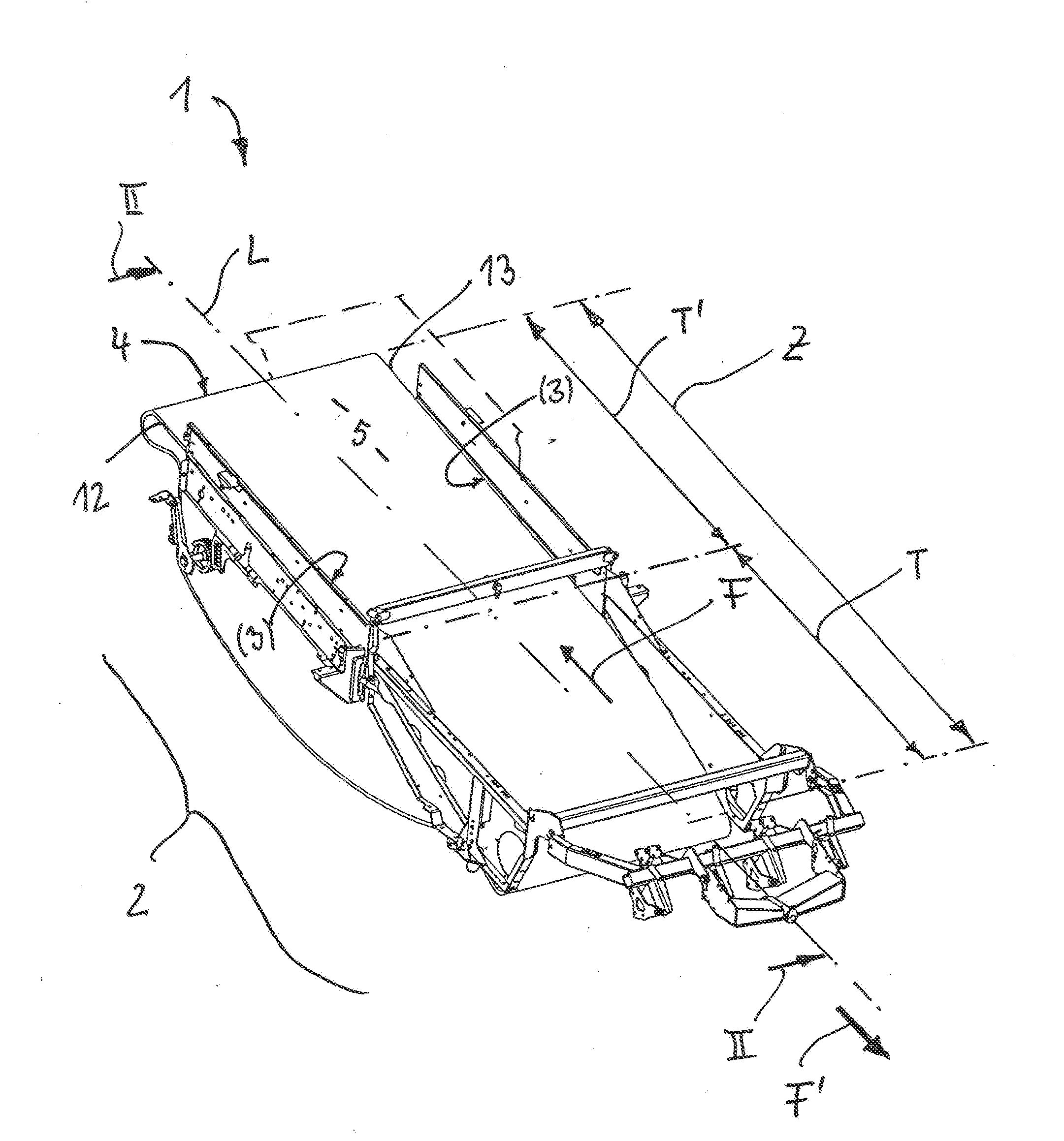
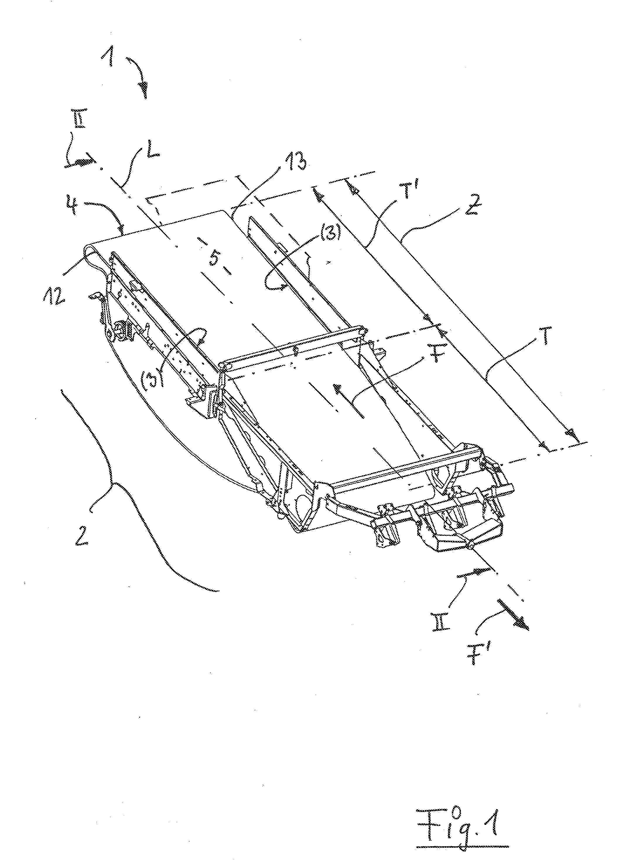
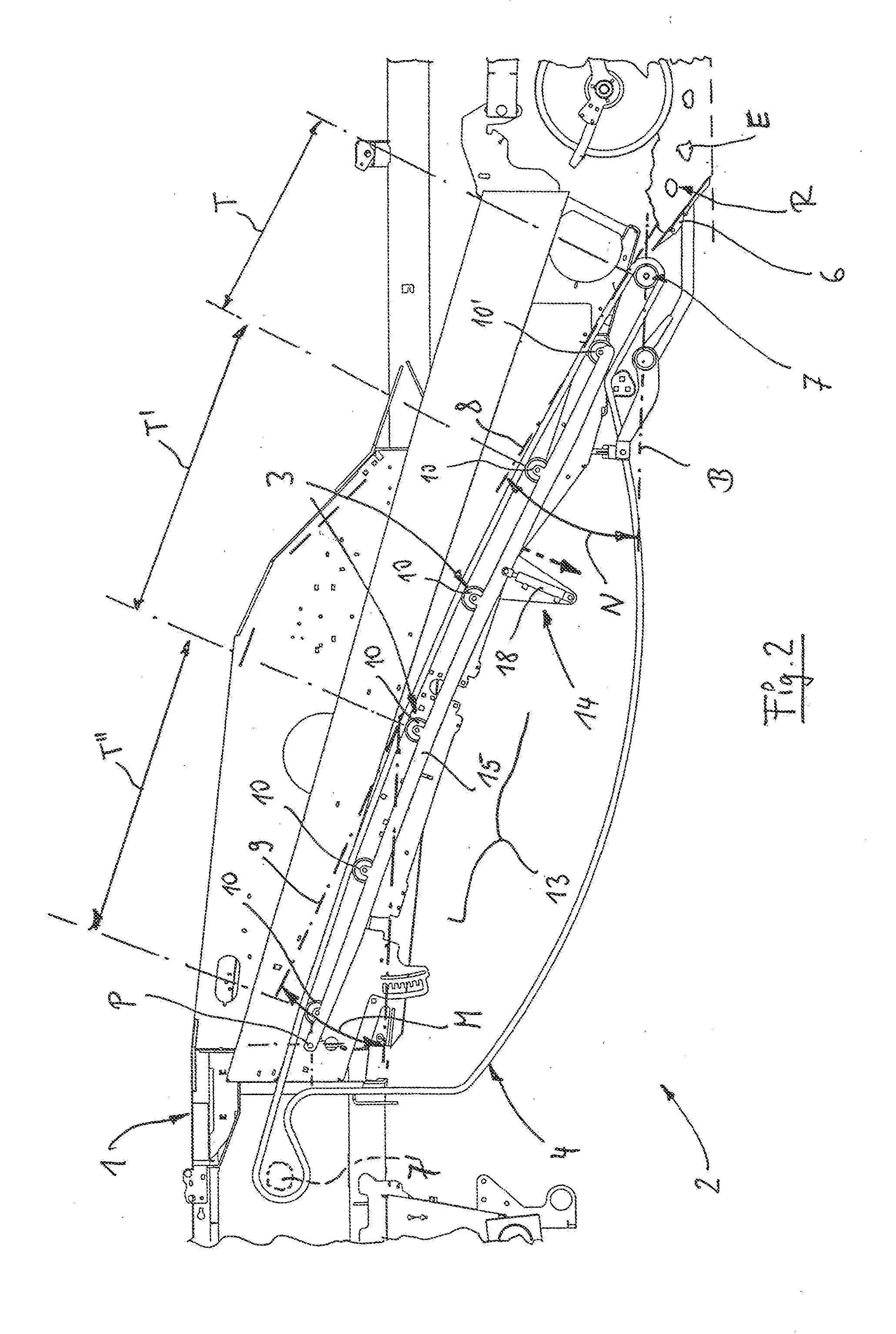
[0039]The concept of this adjusting device 13, 13′ provides that the respective guide elements 3 or 10, 10′ are supported so as to be movable each individually or jointly. In the adjusting device 13 illustrated in FIG. 2, it is provided that the guide elements 3 or 10, 10′ form a jointly adjustable group.

[0040]In the configuration of the adjusting device 13 according to FIG. 2 and FIG. 3, the guide rollers 10, 10′ are secured on a support rail 15 that is connected to the adjusting member 14. This support rail 15 provides the possibility that upon its displacement about a terminal pivot point P the guide elements 10, 10′ provided between the pivot point P and the opposite end of the support rail 15 are also moved and thereby the conveying stretch sections T, T′, T″ defined within the conveying stretch 5 are changed such that optimal conveying slants are adjusted for the processing step. In the illustrated embodiment according to FIGS. 2 and 3, the terminal pivot point P is positioned...

second embodiment

[0041]In FIGS. 4 and 5, the adjusting device 13′ is illustrated. At least one of the guide rollers 10, 10′ is supported on at least two support sections 16, 17 that are movable by the at least one adjusting member 14′ relative to each other. In the illustrated embodiment, on the support sections 16, 17 the respective groups of guide rollers 10 are illustrated wherein the latter or the support sections 16, 17 are moved in the respective lifting direction H′ by the action of the adjusting member 14′ that is also embodied as a hydraulic cylinder 18. In this connection, it is apparent that the support sections 16, 17 may be connected in the area of a connecting joint 23 so that a movement into the spread-apart position (FIG. 5) or a return from this position (FIG. 4) is possible.

[0042]For an advantageous simultaneous displacement of the support sections 16, 17, the connecting joint 23 interacts with a pivot support unit 24 that is located at the opposite end of the support section 16 an...


PUM


Abstract

A harvester for potatoes, beets and other root crops has digging shares arranged in a leading position in the travel direction of the harvester. A screen conveyor receiving a harvested mix and conveying the harvested mix in a conveying direction opposite to the travel direction is provided. The screen conveyor has a screen conveyor belt and guide elements supporting laterally the screen conveyor belt. The screen conveyor belt has a upwardly facing conveying stretch and a leading return pulley proximal to the digging shares. The conveying stretch forms a screening zone that, at least in the area of the leading return pulley, is oriented so as to ascend in the conveying direction. The screen conveyor belt is adjustable to different conveying slants in the area of the conveying stretch.

Description

BACKGROUND OF THE INVENTION[0001]The invention relates to a harvester for potatoes, beets and other root crops, comprising a screen conveyor receiving a harvested mix, wherein the screen conveyor has at least one screen conveyor belt that can be supported by lateral guide elements, respectively, wherein at least one conveying stretch positioned at the top and movable opposite to the travel direction of the harvester forms a screening zone that at least in the area of a return pulley that adjoins the leading digging shares can be oriented so as to ascend in the conveying direction.[0002]Machines for harvesting potatoes, beets and other root crops are based on various embodiments of mechanical apparatus with which the harvested crop removed from the soil is separated from entrained admixtures such as stones, soil clods and similar admixed parts. In a system disclosed in DE 10 41 718 the harvested mix is lifted from a soil ridge by means of a digging share and is transferred by a conve...

Claims


Application Information

Patent Timeline
Patent Type & Authority Applications(United States)
IPC IPC(8): A01D17/00
CPCA01D17/00A01D17/10A01D2017/103
Inventor KALVERKAMP, KLEMENS
Owner GRIMME LANDMASCHFAB
Why Eureka
Try Eureka