Electronic equipment and expansion apparatus thereof

Inactive Publication Date: 2013-06-20
COMPAL ELECTRONICS INC
View PDF12 Cites 5 Cited by
  • Summary
  • Abstract
  • Description
  • Claims
  • Application Information

AI Technical Summary

Benefits of technology

The invention is an expansion apparatus with a fan on the base and a cooling channel in the supporter. It has an airflow guiding structure in the cooling channel that guides the airflow generated by the fan to flow through the channel and cool the electronic apparatus. This improves the efficiency of cooling for the electronic equipment.

Problems solved by technology

However, when the tablet PC performs operations having higher performance requirement, working efficiency of electronic chips therein is also improved, and improvement of the working efficiency generally leads to a large amount of heat produced during the operations, such that the expansion apparatus has to be configured with an additional cooling system to assist cooling the tablet PC.
However, the cooling channel of the above patent is fixed, and no fan is configured in internal of the expansion apparatus.
However, the cooling channel of the above patent is also fixed, and no fan is configured in internal of the cooling base.
Moreover, in the above patent, the connector is not configured to the cooling base to connect the tablet PC.

Method used


Image

  • Electronic equipment and expansion apparatus thereof
  • Electronic equipment and expansion apparatus thereof
  • Electronic equipment and expansion apparatus thereof

Examples


Embodiment Construction

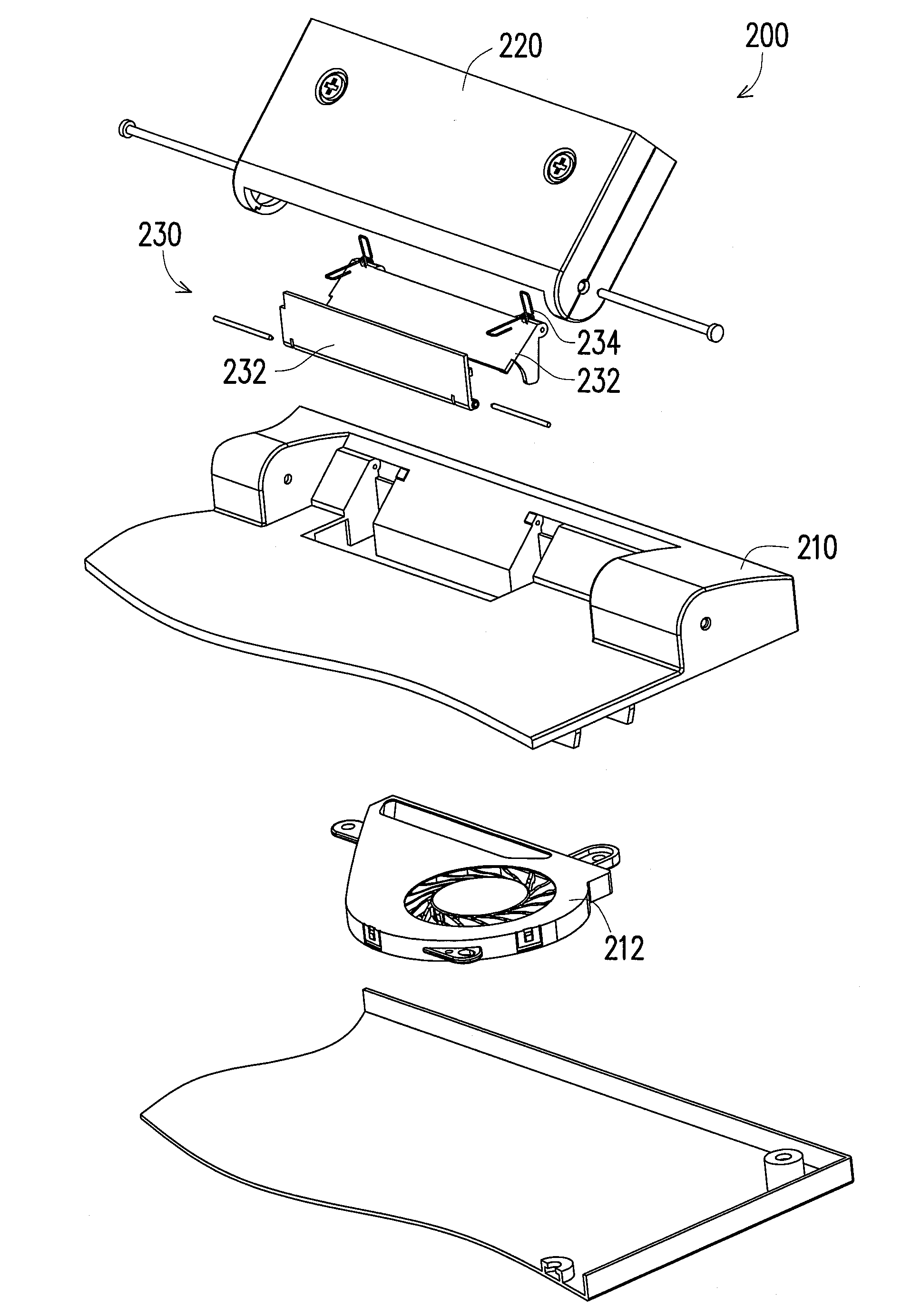
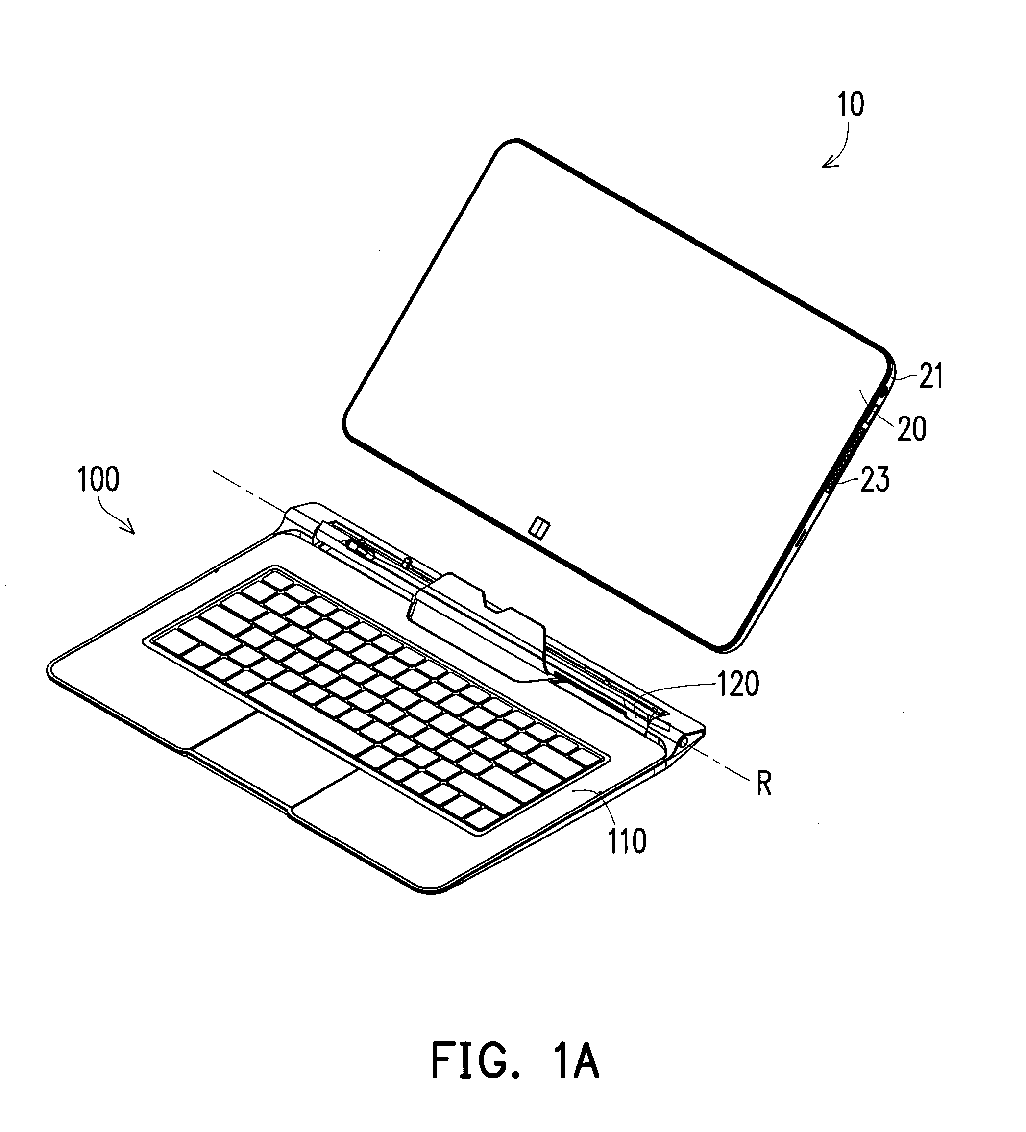
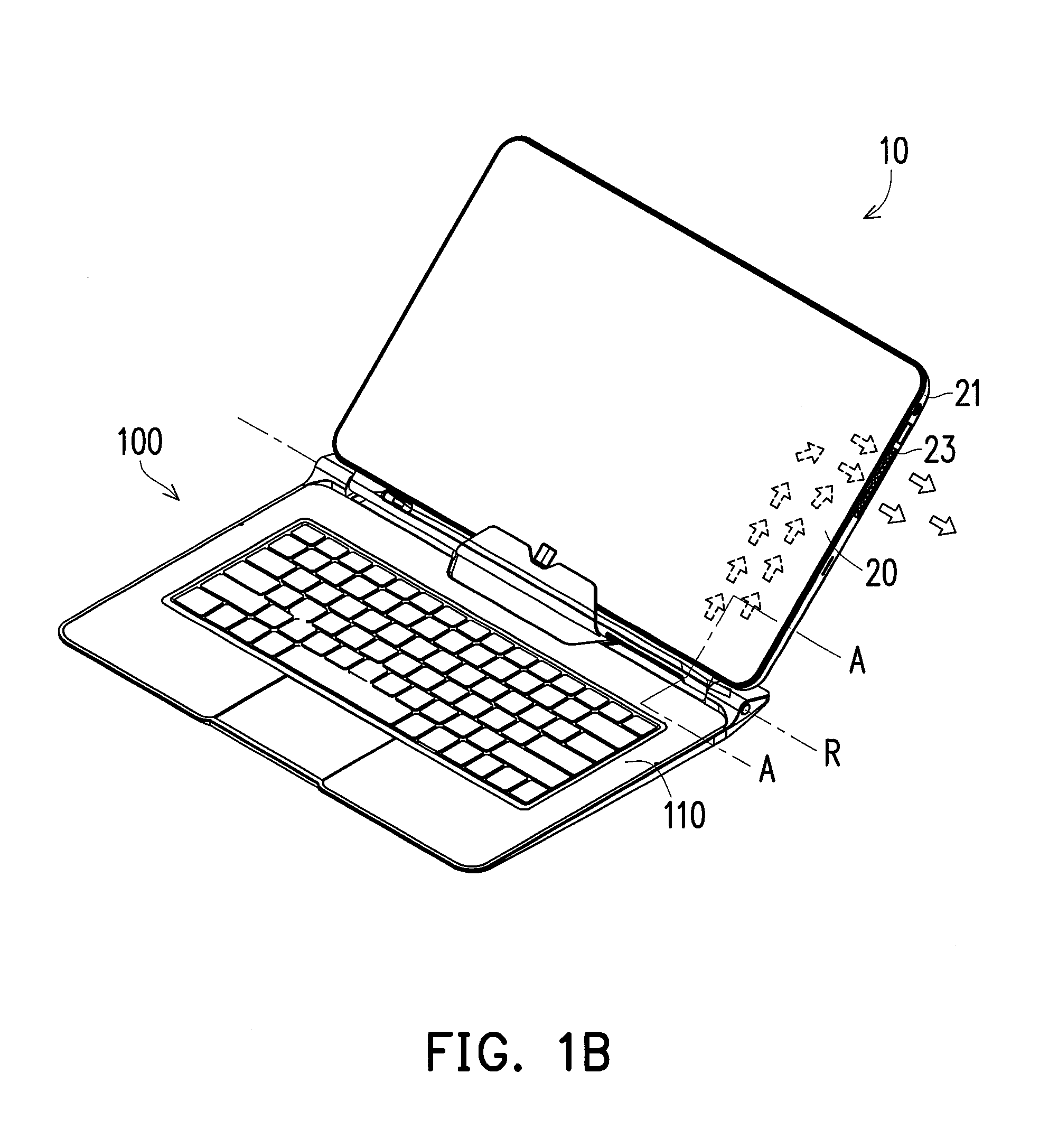
[0040]FIG. 1A is a schematic diagram of an expansion apparatus and an electronic apparatus before assembling according to an embodiment of the invention. FIG. 1B is a schematic diagram of the expansion apparatus and the electronic apparatus of FIG. 1A in a combination state. FIG. 2 is an exploded view of a part of the expansion apparatus of FIG. 1A. FIG. 3A is a cross-sectional view of the electronic apparatus and the expansion apparatus of FIG. 1B along a line A-A. Referring to FIG. 1A to FIG. 3A, the electronic equipment 10 of the present embodiment includes an electronic apparatus 20 and an expansion apparatus 100. The expansion apparatus 100 is adapted to the electronic apparatus 20. In the present embodiment, the electronic apparatus 20 can be a tablet PC or a flat panel display. The expansion apparatus 100 includes a base 110, a supporter 120 and an airflow guiding structure 130. The base 110 has a first fan 112 disposed therein. The supporter 120 is pivoted to the base 110 al...


PUM


Abstract

An expansion apparatus suitable for an electronic apparatus is provided. The expansion apparatus includes a base, a supporter and an airflow guiding structure. The base has a first fan disposed therein. The supporter is pivoted to the base along a rotating axis and has a cooling channel. The cooling channel has a first port and a second port opposite to the first port. When the electronic apparatus is assembled to the supporter, the second port of the cooling channel faces to the electronic apparatus. The airflow guiding structure is disposed between the supporter and the base movably. When the supporter is pivoted relative to the base to an expanded state, an active airflow generated by the first fan is guided by the airflow guiding structure to pass through the base and the electronic apparatus. An electronic equipment including the expansion apparatus is also provided.

Description

CROSS-REFERENCE TO RELATED APPLICATION[0001]This application claims the priority benefits of U.S. provisional application Ser. No. 61 / 578,211, filed on Dec. 20, 2011 and U.S. provisional application Ser. No. 61 / 650,452, filed on May 22, 2012. The entirety of the above-mentioned patent applications is hereby incorporated by reference herein and made a part of this specification.BACKGROUND[0002]1. Technical Field[0003]The invention relates to an expansion apparatus. Particularly, the invention relates to an expansion apparatus capable of guiding airflow.[0004]2. Related Art[0005]Along with quick development of electronic technology, various electronic products have been widely used in our work and daily life. Electronic components in the electronic product may produce heat during operations of the electronic components. In order to maintain normal operations of the electronic components, heat dissipation aperture are generally formed on a casing of the electronic product, or a fan is ...

Claims


Application Information

Patent Timeline
IPC IPC(8): H05K7/20
CPCG06F2200/202G06F1/203G06F1/1632H05K7/20145
Inventor LIU, SHIH-HUEISHIH, CHUN-JENWANG, CHING-HSUANCHEN, PAN-JENCHEN, PO-HAN
Owner COMPAL ELECTRONICS INC
Why Eureka
Try Eureka