High-frequency heating apparatus

Inactive Publication Date: 2005-03-22
PANASONIC CORP
View PDF5 Cites 0 Cited by
  • Summary
  • Abstract
  • Description
  • Claims
  • Application Information

AI Technical Summary

Benefits of technology

The present invention addresses the above-discussed problems, and aims to ensure electrical insulation reliably and improve cooling efficiency of the high-voltage capacitor, while reducing a number of working steps as well as amount of waste in the manufacturing processes.
A high-frequency heating apparatus of the present invention is provided with an air guide having a barrier wall located between a high-voltage transformer and a high-voltage capacitor, the barrier wall of the air guide being reduced in thickness partially to form a plastic hinge, which is bent either manually or automatically after high-voltage terminals of the high-voltage capacitor and the like are wired, so that an end flap extending from the bent hinge isolates the high-voltage carrying terminals of the high-voltage capacitor and the like from a dead metal part such as an outer enclosure, and provides for an electrical insulation. The invention also reduces substantially time and waste that have been needed for placement of plastic sheets for the purpose of electrical insulation in the process of manufacturing high-frequency heating apparatuses. Furthermore, since the plastic end flap covering the high voltage terminals bears a cautionary marking, it can elicit attention of a service personnel and user against electric shock before he / she comes to contact with the terminals of the high-voltage capacitor and the like.

Problems solved by technology

The increase in size of plastic sheet 3 makes the work of placing it difficult, and increases cost of the material.
Besides, since plastic sheet 3 is stuck with glue or adhesive material, it is liable to fail the electrical insulation when it loses the adhesive property and comes off the position due to deterioration over time.
This results in a considerable amount of waste matter at the same time.
If the molding dies are provided with a slide core or the like to avoid the tapered thickness, it makes a structure of the molding dies complex, shortens a useful life of the molding dies, and increases a labor and cost required for maintenance of the molding dies.
This also gives rise to a problem of substantially reducing cooling efficiency of high-voltage capacitor 2, because the cooling air reflected by high-voltage transformer 6 turns to hot air as it receives the heat of high-voltage transformer 6.
In addition, the conventional structure provided with separately mounted insulation cover 8, as shown in FIG. 9, increases a number of components due to the addition of insulation cover 8, and reduces working efficiency in the process of assembly.
Moreover, since insulation cover 8 has a function of rectifying the cooling air, it needs to be considerably large in size, and therefore giving rise to another problem of increase in cost of the material.

Method used


Image

  • High-frequency heating apparatus
  • High-frequency heating apparatus
  • High-frequency heating apparatus

Examples


first exemplary embodiment

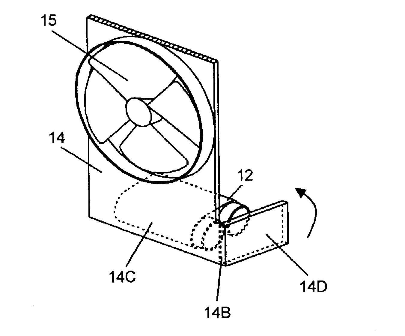
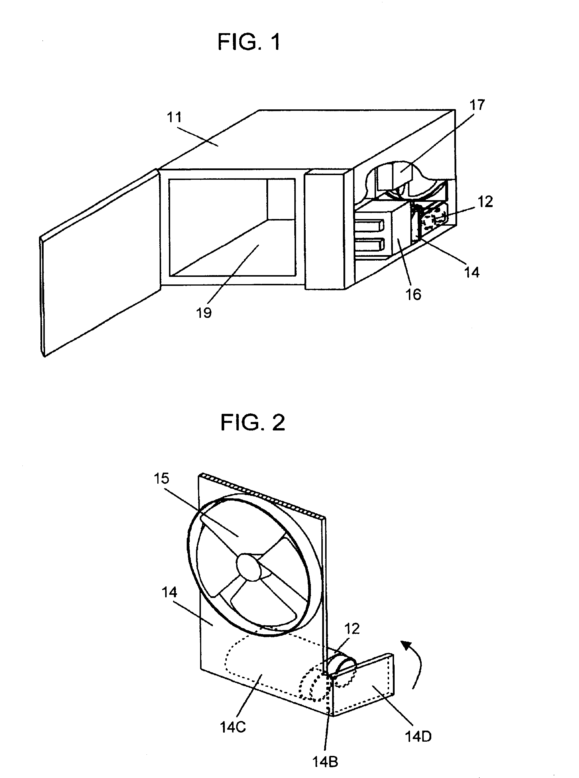
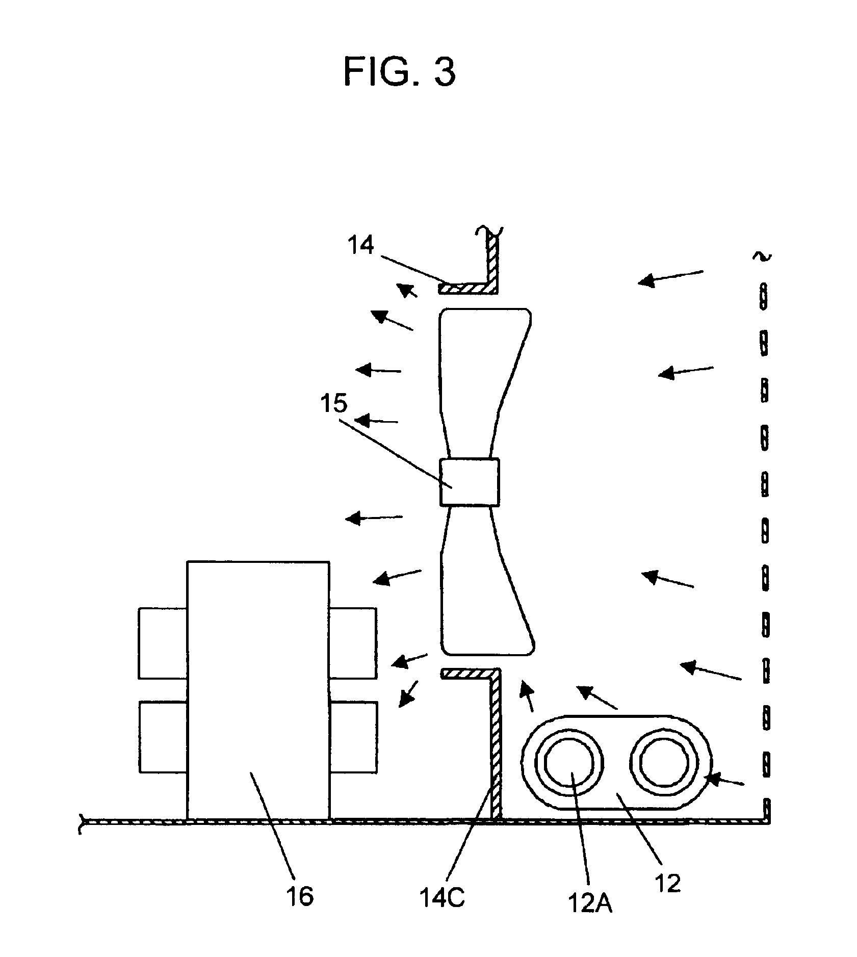
FIG. 1 through FIG. 3 show a high frequency heating apparatus according to the first exemplary embodiment of this invention, wherein FIG. 1 is a partially sectioned perspective view, FIG. 2 is an enlarged perspective view showing a main portion, and FIG. 3 is sectional view showing the main portion.

In FIG. 1 through FIG. 3, high-voltage capacitor 12 and high-voltage transformer 16 supplies electric power of a boosted voltage to magnetron 17, which heats food placed in heating chamber 19. Air guide 14 is provided with barrier wall 14C between high-voltage transformer 16 and high-voltage capacitor 12, and barrier wall 14C is provided with plastic hinge 14B having a partially reduced wall thickness. Plastic hinge 14B is so formed that, when it is bent, end flap 14D is located in a space between terminal 12A of high-voltage capacitor 12 and outer enclosure 11 defining a dead metal part.

According to this exemplary embodiment, the structure described above easily and reliably ensures elec...

second exemplary embodiment

FIG. 4 is an enlarged view of a main area around air guide 14 provided with plastic hinge 14B and high-voltage capacitor 12 according to the second exemplary embodiment of this invention. This embodiment differs from the structure of the first exemplary embodiment in respect that end flap 14D is located on a locus where outer enclosure 11 slides through when being installed, and thereby plastic hinge 14D is bent automatically by a movement of outer enclosure 11 as it is installed. Components having the same reference numerals as those of the first exemplary embodiment have the same structures, and their details are therefore skipped.

First, when outer enclosure 11 is being installed, it comes in contact to end flap 14D of air guide 14 extending beyond a moving locus of outer enclosure 11, and pushes to bend plastic hinge 14B. As a result, bent end flap 14D of plastic hinge 14B is moved in place between terminal 12A of high-voltage capacitor 12 and outer enclosure 11 of a dead metal p...


PUM


Abstract

A high-frequency heating apparatus includes an outer enclosure, a high voltage generator such as a high-voltage capacitor, and an air guide, wherein the air guide is provided with a plastic hinge formed by partially reducing a wall thickness thereof. The invented structure can bend the plastic hinge to locate an end flap of air guide in a space between a terminal of the high-voltage capacitor and the outer enclosure defining a dead metal part, to easily ensure electrical insulation between the terminal and the outer enclosure without dependent on variations in quality of workmanship in the manufacturing process. In addition, it can reduce a number of working processes as well as amount of waste since all it requires is to bend the plastic hinge to provide the electrical insulation.

Description

FIELD OF THE INVENTIONThe present invention relates to a high-frequency heating apparatus having a structure designed to easily and reliably ensure electrical insulation of electric terminals charged with high voltage such as those of a high-voltage transformer and a high-voltage capacitor from electrically dead metal parts including a chassis and an outer enclosure that are accessible to a user. The structure comprises a plastic member having a plastic hinge, which is bent either manually or automatically as the outer enclosure is installed after the high-voltage carrying terminals are wired, so that an end flap extending from the bent plastic hinge is located in a space between the high-voltage carrying terminals and the dead metal parts.BACKGROUND OF THE INVENTIONIn a conventional high-frequency heating apparatus, it is a general practice to separate high voltage carrying parts such as terminals of a high-voltage capacitor from a dead metal part such as an outer enclosure, which ...

Claims


Application Information

Patent Timeline
IPC IPC(8): H05B6/80H05B6/66F24C7/02H05B6/64
CPCH05B6/642
Inventor YAMAGUCHI, TAKAHIDE
Owner PANASONIC CORP
Why Eureka
Try Eureka