
Apparatus for cooling steel sheet

Pending Publication Date: 2022-01-13
POSCO
View PDF0 Cites 0 Cited by
  • Summary
  • Abstract
  • Description
  • Claims
  • Application Information

AI Technical Summary

Benefits of technology

The patent aims to improve the cooling efficiency and surface quality of a steel sheet, which leads to an increase in production efficiency.

Problems solved by technology

A period, in which such a cooling process is performed, may be significantly limited.
In this case, a large amount of cooling fluid is used.
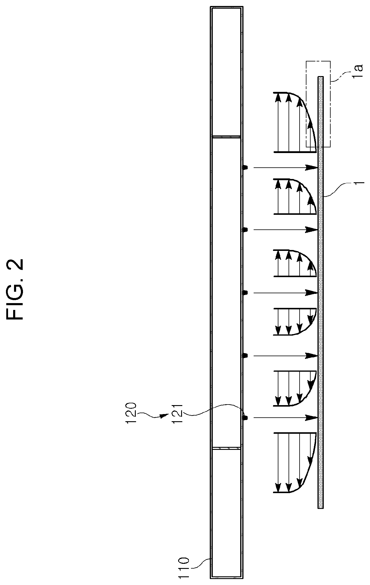
Due to the flow rate increased in the direction toward the edge of the steel sheet, surface defects such as a blowing mark may occur on the edge of the steel sheet.

Method used


Image

  • Apparatus for cooling steel sheet
  • Apparatus for cooling steel sheet
  • Apparatus for cooling steel sheet

Examples


Embodiment Construction

[0058]In order to facilitate an understanding of the description of example embodiments of the present disclosure, the same reference numerals are used for the same elements in the accompanying drawings, and related elements among elements performing the same function in each example embodiment are denoted by the same number or the number of extension.

[0059]Further, in order to clarify the gist of the present disclosure, a description of elements and techniques well known in the related art will be omitted, and the present disclosure will be described in detail with reference to the accompanying drawings.

[0060]It is to be understood, however, that the spirit and scope of the present disclosure are not limited to the example embodiments illustrated, but other forms may be suggested by those skilled in the art while specific components are added, changed, and deleted, which also included within the scope of the same idea as the present disclosure.

[0061]In accompanying drawings, an X-a...


PUM

PropertyMeasurementUnit
Angleaaaaaaaaaa
Angleaaaaaaaaaa
Angleaaaaaaaaaa

Abstract

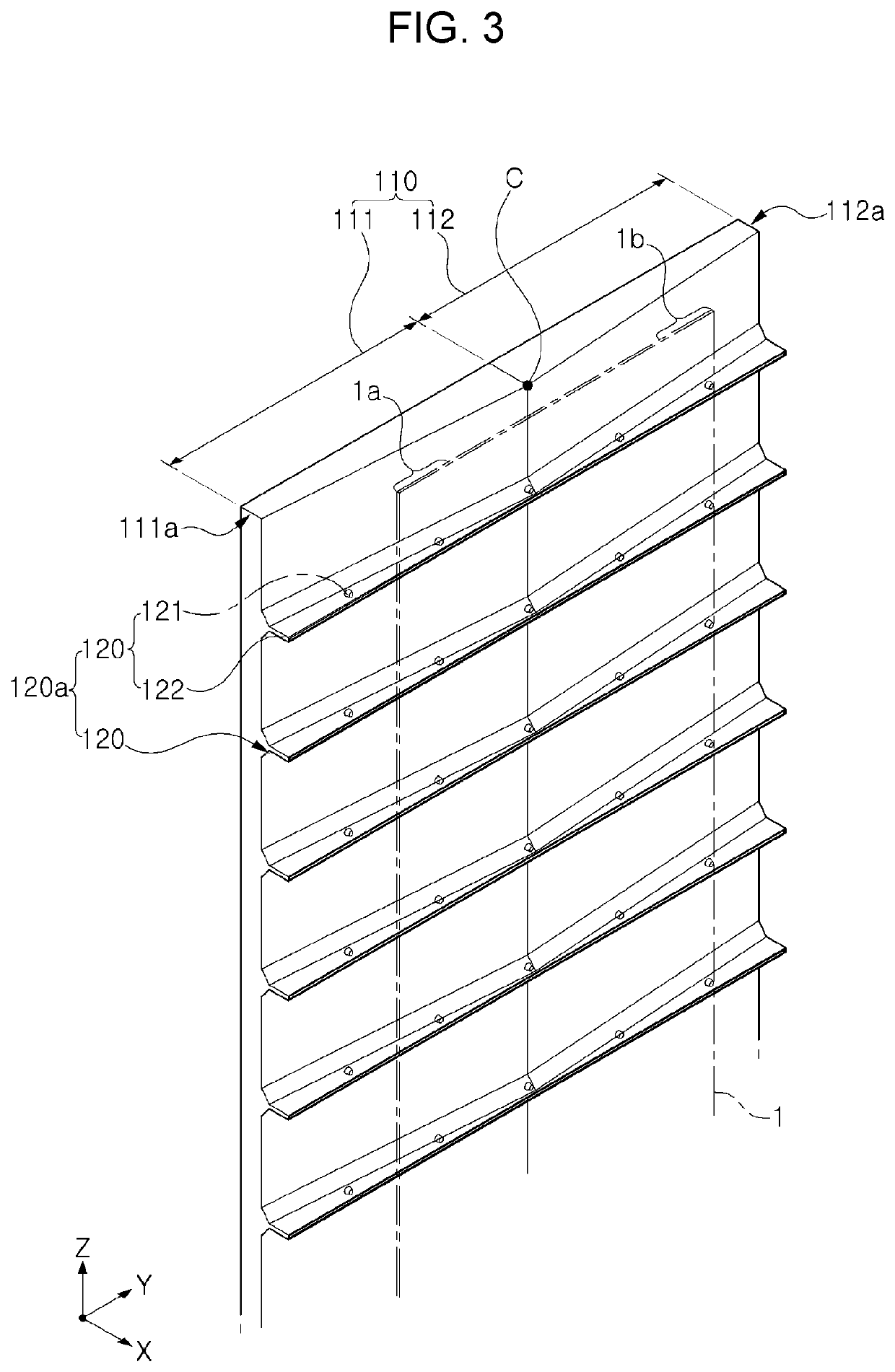
An apparatus for cooling a steel sheet includes: an apparatus body provided spaced apart from a steel sheet in the conveying path of the steel sheet; and a cooling unit provided in the apparatus body to supply a cooling fluid. The apparatus body includes: a first edge body that faces a first edge portion extending a certain distance from one side end of the steel sheet toward the center of the steel sheet; and a second edge body that faces a second edge portion extending a certain distance from the other side end of the steel sheet toward the center of the steel sheet. The first and second edge bodies may have stepped cross-sections in a direction perpendicular to the conveying direction of the steel sheet.

Description

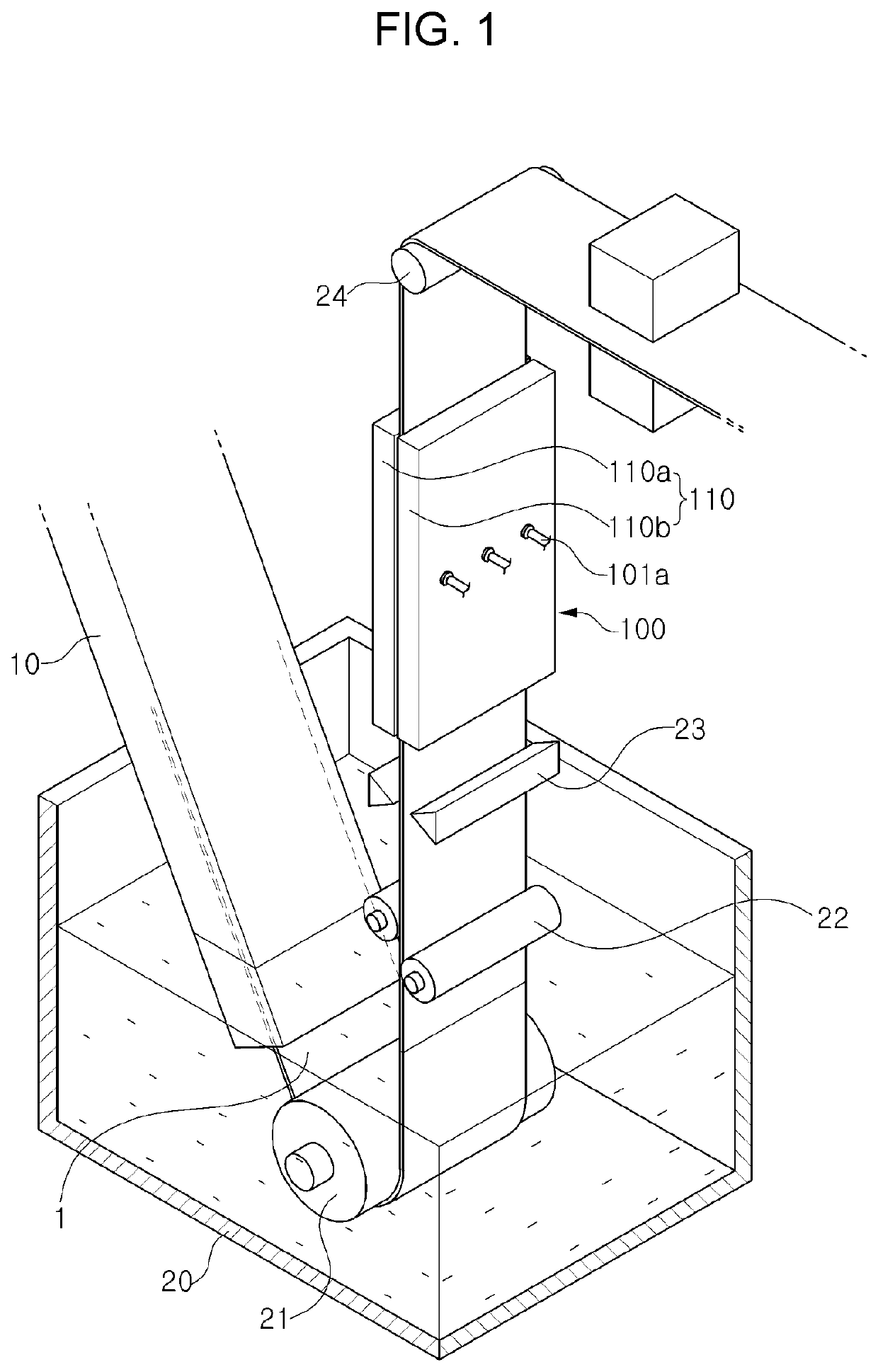
TECHNICAL FIELD[0001]The present disclosure relates to an apparatus for cooling a steel sheet.BACKGROUND ART[0002]When a surface of a steel sheet formed of aluminum or steel is plated with zinc or a zinc-alloy, a cooling process is performed to solidify a plated layer on the surface of the steel sheet.[0003]Conventionally, such a cooling process maybe performed during conveyance of a steel sheet to post-processing or during the post-processing. A period, in which such a cooling process is performed, may be significantly limited.[0004]Therefore, water or air (hereinafter referred to as “cooling fluid”) may be supplied to a steel sheet to perform strong cooling within an allowable cooling process period. In this case, a large amount of cooling fluid is used.[0005]Since the cooling fluid colliding with the surface of the steel sheet is discharged along an edge of the steel sheet in a width direction, a flow rate of the cooling fluid tends to be increased in a direction toward the edge ...

Claims


Application Information

Patent Timeline
IPC IPC(8): B21B45/02
CPCB21B45/0233B21B2045/0212C23C2/40B05B1/205B05B9/035B05B1/02B05B14/30B05B13/0207B05B1/262C23C2/004C23C2/00344C23C2/0038C23C2/29C23C2/0035C23C2/26B05B1/14C23C2/261C23C2/20
Inventor JEONG, HAE-KWONLEE, JAE-HWACHOI, WON-SUKJOO, KYO-HALEE
Owner POSCO
Learn More