Congestion control system, congestion control method, and communication unit

a technology of congestion control and communication unit, applied in the field of congestion control technique, can solve problems such as uniform transmission rate between the two reaction points

Inactive Publication Date: 2013-06-20
NEC CORP +1
View PDF5 Cites 9 Cited by
  • Summary
  • Abstract
  • Description
  • Claims
  • Application Information

AI Technical Summary

Benefits of technology

[0023]According to the present invention The partiality of the transmission rate among the plurality of reaction points becomes able to be restrained in case of control of being congestion which is based on the method of the congestion notice.

Problems solved by technology

It is not desirable because it causes ununiformity of the transmission rates among the plurality of reaction points (a plurality of flows).
However, it would be understood that the ununiformity of the transmission rate occurs between the two reaction points.

Method used


Image

  • Congestion control system, congestion control method, and communication unit
  • Congestion control system, congestion control method, and communication unit
  • Congestion control system, congestion control method, and communication unit

Examples


Embodiment Construction

[0041]Hereinafter, the exemplary embodiment of the present invention will be described with reference to the attached drawings.

1. OUTLINE

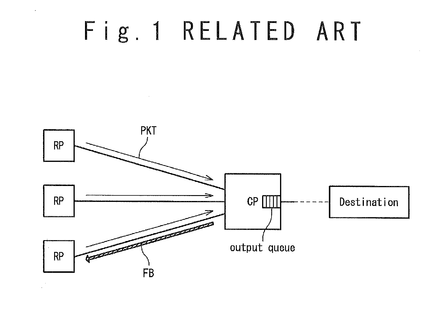
[0042]FIG. 4 is a schematic diagram showing a configuration of a congestion control system 1 according to a present exemplary embodiment. The congestion control system 1 is provided with a plurality of reaction points (RP) 10, a transmission destination 20 and a congestion point (CP) 30.

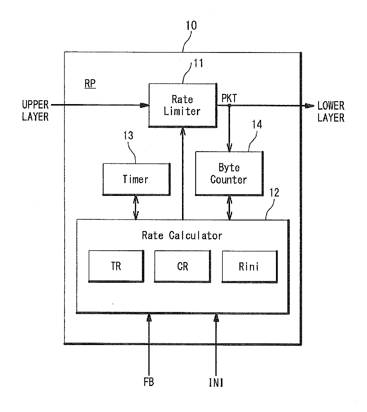
[0043]The reaction point 10 is typically contained in a transmitting section of a terminal which is connected with a network. It should be noted that it is allowed in IEEE802.1Qau that a transmitting section of one terminal is provided with a plurality of the reaction points 10. The transmission destination 20 is a terminal typically. The reaction points 10 and the transmission destination 20 are connected with the network. Each of the plurality of reaction points 10 transmits a packet PKT to the transmission destination 20.

[0044]The congestion point 30 is arranged ...


PUM


Abstract

A congestion control system is provided with a plurality of reaction points, each of which is configured to transmit a packet to a transmission destination; and a congestion point configured to receive the packets transmitted from the plurality of reaction points. When detecting congestion in itself, the congestion point samples each of the received packets based on a predetermined algorithm, and transmits a feedback message to the reaction point as a transmission source of the sampled packet. Each of the plurality of reaction points controls a target rate based on a reception situation of the feedback message, and sets the target rate to an initial value at an initialization timing which does not depend on the feedback message.

Description

TECHNICAL FIELD[0001]The present invention is related to a congestion control technique. More particularly, the present invention is related to a congestion control technique of a congestion notice (CN) method.RELATED ART[0002]In recent years, the use of a data center is expanding in which servers are concentrated in one base station to provide computer resources to individuals and enterprises. In the data center, a network is required to have flexibility and expandability, by connecting a great deal of servers while securing high-speed processing, low delay, and a low discard rate.[0003]In IEEE802.1, the technique, “data center bridging (DCB)” is set to extend a conventional MAC bridge function while satisfying the above requirement. As one elemental technique, a “congestion notice (CN)” is being standardized in IEEE802.1Qau. For the details of IEEE802.1Qau, refer to Non-Patent Literature 1.[0004]In IEEE802.1Qau, a transmission source (a transmission point) of a packet is called a ...

Claims


Application Information

Patent Timeline
Patent Type & Authority Applications(United States)
IPC IPC(8): H04L12/56
CPCH04L47/11H04L47/26
Inventor KAMIYA, SATOSHIYAMAMOTO, MIKI
Owner NEC CORP
Why Eureka
Try Eureka