Apparatus, system, and method for facilitating use of thin flexible scrims in a grid-type suspended ceiling

a technology of grid-type suspended ceilings and flexible scrims, which is applied in the direction of ceilings, walls, building repairs, etc., can solve the problems of unsatisfactory expense, and achieve the effect of reducing cost, convenient and fast installation process, and convenient and fast adaptation

Inactive Publication Date: 2013-06-27
USG INTERIORS INC
View PDF13 Cites 6 Cited by
  • Summary
  • Abstract
  • Description
  • Claims
  • Application Information

AI Technical Summary

Benefits of technology

[0005]Pursuant to the various exemplary preferred embodiments, ceiling panels for use in a grid-type suspended ceiling each comprise a thin flexible scrim that is of insufficient rigidity to consistently maintain a substantially planar form when installed in the grid-type suspended ceiling. These embodiments also present a rigidizing and engagement member that attaches to only a relatively minor portion of the thin flexible scrim and that is configured and arranged to substantially increase and maintain rigidity of the thin flexible scrim such that the thin flexible scrim will consistently maintain a substantially planar form when installed in the grid-type suspended ceiling and that will also serve to engage at least one grid runner of the grid-type suspended ceiling to thereby maintain the thin flexible scrim in an installed position within the grid-type suspended ceiling.
[0006]Pursuant to one exemplary embodiment, the rigidizing and engagement member can comprise a beam having a kerf formed in opposing ends thereof. When secured to the thin flexible scrim, these kerfs can serve to receive a corresponding portion of a grid runner to thereby aid in retaining the resultant ceiling panel in an installed position even as the beam itself lends sufficient rigidity to the scrim to thereby maintain the scrim in a substantially planar form following installation.
[0007]Pursuant to another exemplary embodiment, the rigidizing and engagement member can comprise a corner piece that engages folded-up walls of the scrim to thereby aid in retaining such walls in a deployed manner. When so retained by the corner piece, these walls provide the desired amount of rigidity. In addition, such a corner piece can be configured and arranged to interact with the grid runners to thereby again serve to maintain the ceiling panel in an installed position. By one approach in this regard, such a corner piece can be configured and arranged to extend outwardly of the perimeter of the scrim in order to rest upon a corresponding grid runner surface. By another approach in this regard, such a corner piece can have one or more notches that serve to receive a corresponding part of the grid runner in order to thereby support the scrim from that grid runner.
[0008]So configured, very thin and quite flexible scrims can be employed in place of traditional ceiling panels. This can contribute greatly to a significantly reduced cost for such a component. Those skilled in the art will also understand and appreciate that these embodiments are readily and easily accommodated at the worksite and hence can contribute to an efficient and speedy installation process. This, in turn, also contributes greatly to yielding a highly cost-effective approach. Those skilled in the art will also appreciate that these embodiments are highly scalable and can be employed with a wide variety of differently sized and differently shaped ceiling panels. It will also be noted that these embodiments will accommodate ready removal of an installed panel, thereby preserving an important design feature of such a component.

Problems solved by technology

There are some application settings, however, where such is not always the case.
For example, there are instances when additional components employed in such a ceiling, such as acoustic batting, negate a need for an exposed ceiling panel that offers much beyond an aesthetically pleasing visage.
In such a case, existing approaches that emphasize the use of rigid ceiling panels can lead to undesirable expense due to the inherent cost of such panels.

Method used


Image

  • Apparatus, system, and method for facilitating use of thin flexible scrims in a grid-type suspended ceiling
  • Apparatus, system, and method for facilitating use of thin flexible scrims in a grid-type suspended ceiling
  • Apparatus, system, and method for facilitating use of thin flexible scrims in a grid-type suspended ceiling

Examples


Embodiment Construction

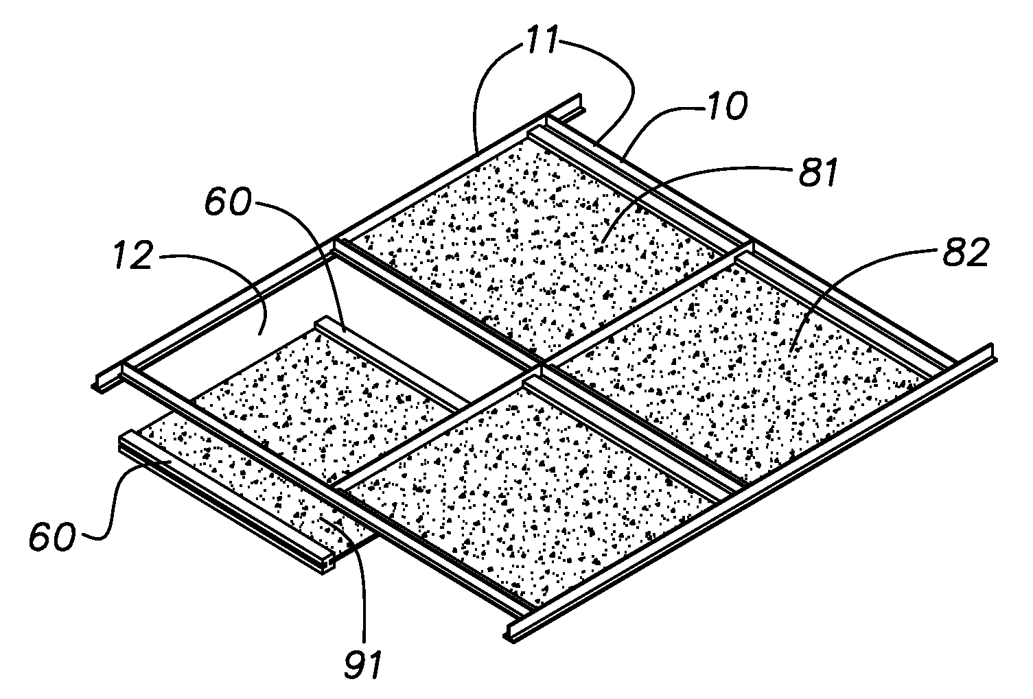
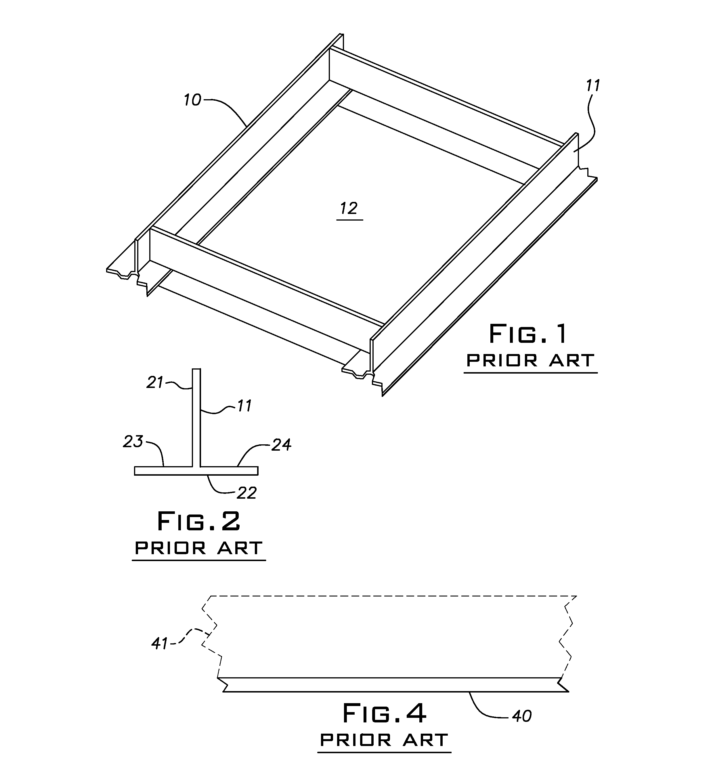
[0033]These and other benefits may become clearer upon making a thorough review and study of the following detailed description. Referring now to the drawings, and in particular to FIGS. 1 and 2, it may be helpful to first briefly describe and characterize a grid-type suspended ceiling 10. Such a ceiling 10 is typically comprised of a plurality of spaced grid runners 11 that are joined one to the other in a manner that defines a plurality of ceiling panel regions 12. These grid runners 11 often have an inverted “T” shaped cross-section that comprises a vertical member 21 and a horizontal member 22 having outwardly extending flanges 23 and 24. The vertical member 21 typically serves as a point of attachment by which the grid runner 11 can be suspended in place. The horizontal member 22, in turn, provides horizontal surfaces upon which ceiling panels are typically placed when installed.

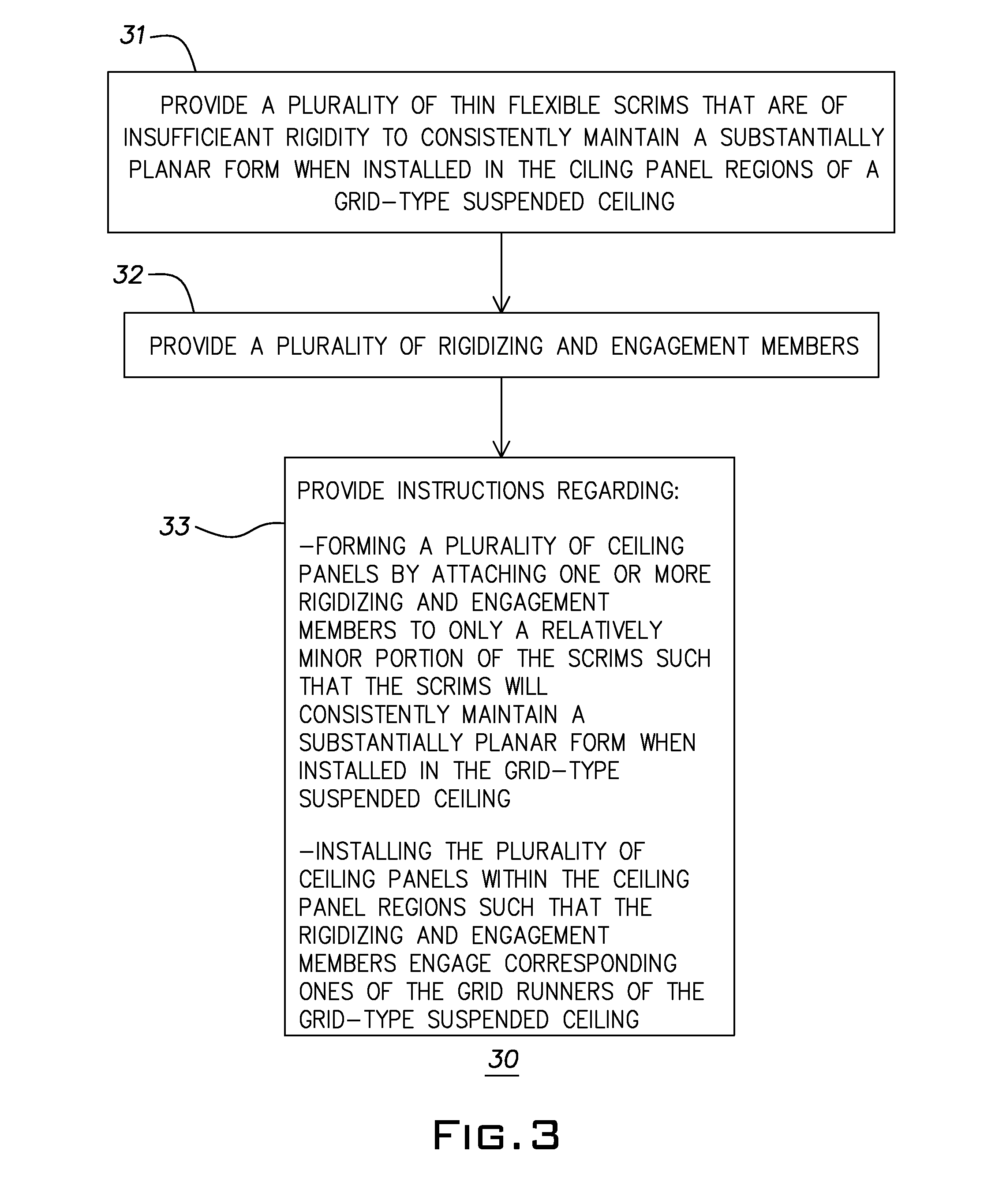
[0034]Referring now to FIG. 3, an overview process 30 which accords with these teachings and embodim...


PUM


Abstract

Ceiling panels for use in a grid-type suspended ceiling (10) each comprise a thin flexible scrim (40) that is of insufficient rigidity to consistently maintain a substantially planar form when installed in the grid-type suspended ceiling. These embodiments also present a rigidizing and engagement member (60, 122, 161) that attaches to only a relatively minor portion of the thin flexible scrim and that is configured and arranged to substantially increase and maintain rigidity of the thin flexible scrim such that the thin flexible scrim will consistently maintain a substantially planar form when installed in the grid-type suspended ceiling and that will also serve to engage at least one grid runner of the grid-type suspended ceiling to thereby maintain the thin flexible scrim in an installed position within the grid-type suspended ceiling.

Description

TECHNICAL FIELD[0001]This invention relates generally to grid-type suspended ceilings.BACKGROUND[0002]Suspended ceilings of various types are known in the art. This includes grid-type suspended ceilings. Suspended ceilings, sometimes also known as a drop or dropped ceiling, typically serve as a secondary ceiling formed to conceal piping, wiring, ductwork, and other exposed construction elements in an area called the plenum. Such ceilings typically consist of a grid-work of spaced grid runners that often have the shape of an upside-down “T” that are suspended on wires from the overhead structure. These channels snap together in a regularly spaced pattern to form corresponding ceiling panel regions.[0003]These ceiling panel regions each typically serve to receive a single ceiling panel (also sometimes known as ceiling tiles) which often simply drop into the grid. Such ceiling panels are supported by the T-shaped grid runners. These ceiling panels themselves usually stay in place and c...

Claims


Application Information

Patent Timeline
Patent Type & Authority Applications(United States)
IPC IPC(8): E04B9/18E04B9/00
CPCE04B9/04E04B9/241E04B9/24E04B9/0435
Inventor GULBRANDSEN, PEDER J.
Owner USG INTERIORS INC
Why Eureka
Try Eureka