Armour assembly

a technology for armour and parts, applied in the field of armour parts, can solve the problems of increasing the likelihood of ballistic projectile disassembly, not providing high general protection from all forms of hazards, and not very effective at defeating certain threats, etc., to achieve effective armour arrangement, reduce the cost and burden of replacing damaged armour, and reduce the effect of cost and burden

Active Publication Date: 2013-06-27
BAE SYSTEMS PLC
View PDF26 Cites 7 Cited by
  • Summary
  • Abstract
  • Description
  • Claims
  • Application Information

AI Technical Summary

Benefits of technology

[0036]An additional advantage of the armour assembly of the present invention is that if one or more of the armour plates gets damaged, only the damaged armour plates need to be replaced, thereby reducing costs and the burden of replacing damaged armour. This is in contrast to prior art arrangements where the entire plate (which is often large and may cover an entire side of a vehicle) needs to be replaced if a portion of it gets damaged. This is a significant feature as individual damaged armour plates may be replaced quickly without the requirement of specialist tools (in preferable embodiments) in a potentially hostile environment where it would be highly undesirable to be travelling in a vehicle with damaged and compromised armour.
[0037]In a preferable embodiment, the frame defines a frame plane, where each of the plurality of armour plates has a longitudinal axis and is releasably mountable to the frame so that each longitudinal axis may be orientated substantially parallel to the frame plane. This preferable embodiment allows a regular array of armour plates to be arranged in the frame which offers a particularly effective armour arrangement against ballistic projectiles, but also allows for simple, quick and easy mounting and unmounting of the armour plates in the frame. In a particularly preferable embodiment, the plurality of armour plates may be orientated so that each armour plate is adjacent to at least one other armour plate. In this embodiment, protection provided by the armour assembly is maximized.
[0038]In one preferable embodiment, each of the plurality of armour plates has a face, and the plurality of armour plates may be orientated so that the face of each armour plate is perpendicular to the face of the at least one other armour plate. In this embodiment the armour plates are orientated in a preferential arrangement that is particularly effective at providing protection from ballistic projectiles, due to the orientation of the edges of the holes in the armour plates.
[0039]The frame preferably has four walls including a top wall, a bottom wall and two side walls extending between the top and bottom walls; and wherein the top wall comprises top guides and the bottom wall comprises bottom guides, and the top and bottom guides are arranged so that each of the plurality of armour plates is releasably mountable in both a top guide and a bottom guide. In this preferable embodiment, the frame has a particularly strong structure whereby the plurality of armour plates are mounted thereon and the risk of disruption of the arrangement of armour plates due to compromise of the frame structure is minimized. In a further preferable embodiment, the top guides are top slots in the top wall and the bottom guides are bottom slots in the bottom wall, wherein each of the slots is arranged to receive one of the plurality of armour plates. In this preferable embodiment, the slots provide a means of guiding the armour plates into and out of frame when mounting and unmounting and provide a secure means of preventing unwanted movement of the armour plates relative to the frame when in position in the frame.
[0040]Further preferably, each of the plurality of armour plates comprises a body portion and a bottom tab extending from the body portion in a direction parallel to the longitudinal axis, where the bottom tab is smaller than the body portion in at least one direction perpendicular to the longitudinal axis; and wherein the bottom tab is receivable in one of the bottom slots of the bottom wall, and where the bottom slot is sized so as to prevent passage of the body portion therethrough. This preferable embodiment provides an improved means of securely retaining the armour plates in the frame and limits further movement along a direction parallel to the longitudinal axes of the plates once a suitable position has been reached.
[0041]Alternatively or additionally, each of the plurality of armour plates comprises a removal tab that facilitates the removal of the armour plate from the frame. In one preferable embodiment the removal tab is configured to be gripped by a hand thereby facilitating manual removal. In an alternative preferable embodiment, the removal tab is configured to be engaged by a removal tool thereby providing a means for removing the armour plates from the frame using a tool which may be automatic and non-manual. In one preferable embodiment, the removal tab extends from the body portion of each armour plate in a direction parallel to its longitudinal axis from an opposite end of the body portion to the bottom tab.

Problems solved by technology

Appliqué armour is routinely used to provide a sacrificial or readily replaceable piece of armour, which defeats certain threats very effectively, but may not provide high levels of general protection from all forms of hazard threats likely to be encountered.
The increase of pressure increases the likelihood of the ballistic projectile disintegrating on impact or being deflected and thereby reducing its energy, and thus its ability to penetrate the armour.
As mentioned above, whilst the addition of armour increases a vehicle's defences against ballistic projectiles, the added weight can impair the vehicle's ability to manoeuvre and travel at its optimal or preferred speed or acceleration rate, even when lighter perforated armour is used.
This is a particular problem when considering vehicles that may be travelling in and out of known safe areas where no or less protection is required, or when travelling in areas where it is undesirable to compromise the vehicle's speed, acceleration or manoeuvrability.

Method used


Image

  • Armour assembly
  • Armour assembly
  • Armour assembly

Examples


Embodiment Construction

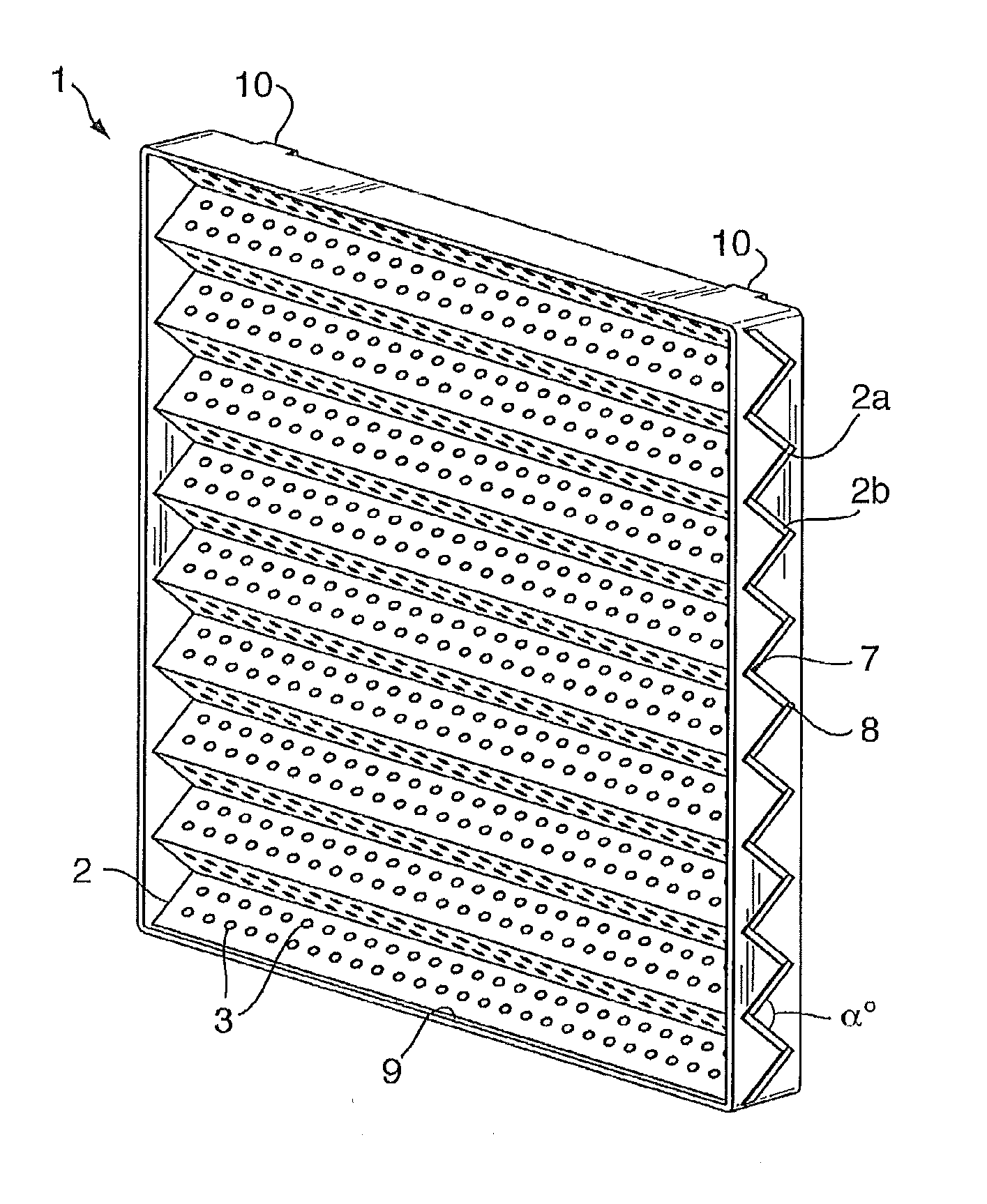
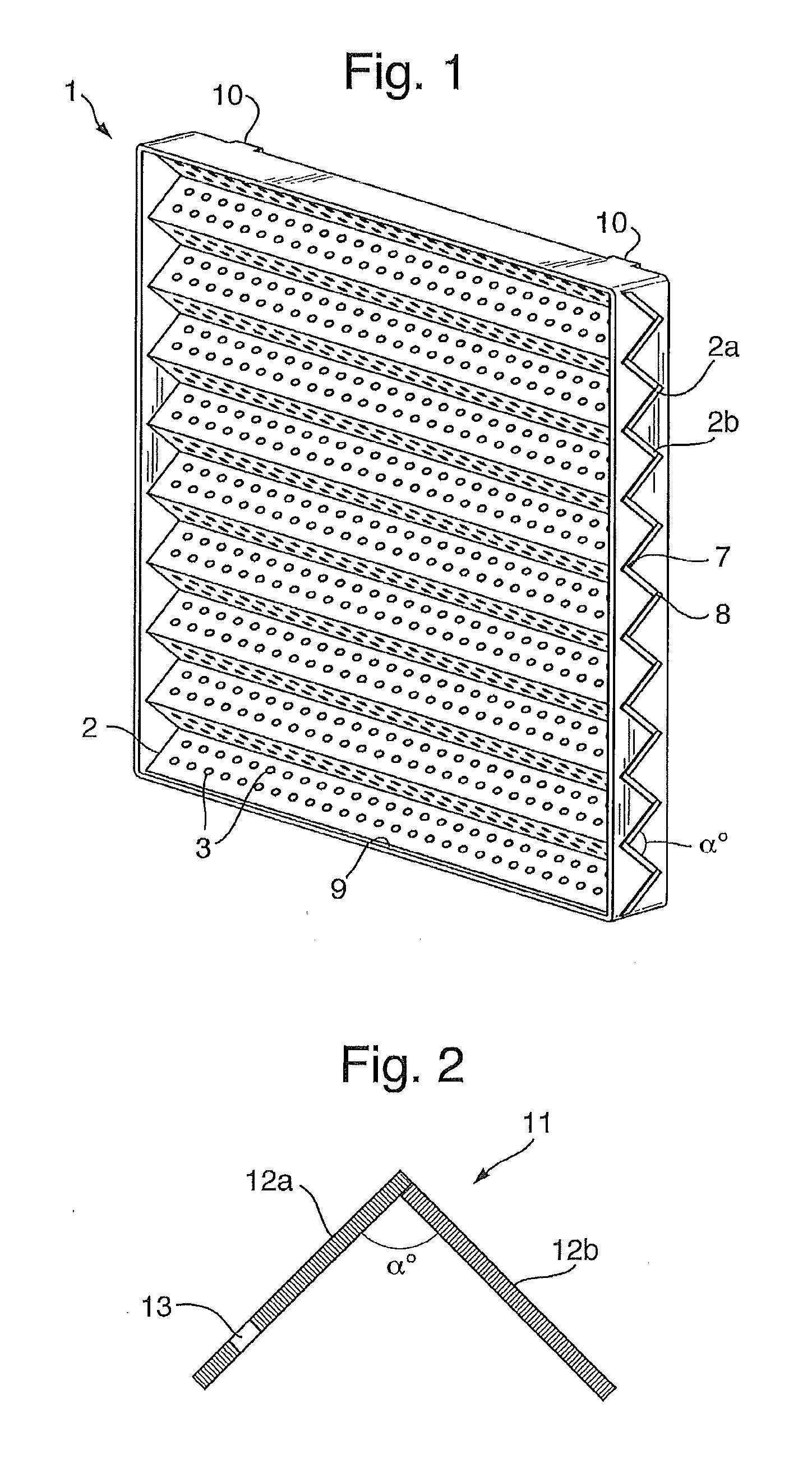
[0055]Turning to FIG. 1, there is provided an armour system 1, which is optionally contained in a housing 9 (or frame) to form an appliqué armour system, or the armour 1 may be directly applied to an existing armour structure. The housing 9 contains a plurality of at least two elements 2, wherein elements 2a,2b are joined at their apex 7 and troughs 8, to form a continuous armour system. The elements 2, comprise a plurality of perforations 3. The housing may be fixed by lugs 10 to a vehicle. The elements 2a and 2b, are set an angle(α) so as to provide a chevron arrangement. The elements 2a, 2b in this arrangement are provided as elongate elements. The device is mounted on the vehicle such that the elements 2, their longest dimension axis is substantially parallel with the ground plane on which the vehicles wheel base is located (see FIG. 4).

[0056]FIG. 2 shows a cross section of elements 12a and 12b angled apart from each other an angle(α), with a perforation 13 located in the elemen...


PUM


Abstract

An armour system, comprising at least two elements, wherein said elements are arranged at an angle(α)°, characterised wherein said at least two elements comprise a plurality of perforations.

Description

[0001]This invention relates to an armour assembly and, more particularly, to an additional armour or appliqué style armour to provide additional protection to the primary armour system and to an armour assembly that is attachable to a vehicle.BACKGROUND[0002]Vehicles, such as military vehicles, sometimes require armour to protect the vehicle and its occupants from harm when the vehicle is in a hostile environment, for example. The type of armour used on a vehicle will primarily depend on the type of anticipated threat, but consideration will also need to be given to the effect of the armour on the vehicle's performance (e.g. the effect on speed and / or manoeuvrability due to the weight of the armour).[0003]Appliqué armour is routinely used to provide a sacrificial or readily replaceable piece of armour, which defeats certain threats very effectively, but may not provide high levels of general protection from all forms of hazard threats likely to be encountered.[0004]It is known to u...

Claims


Application Information

Patent Timeline
Patent Type & Authority Applications(United States)
IPC IPC(8): F41H5/02F41H5/013
CPCF41H5/013F41H5/023F41H5/02F41H5/026
Inventor LIVESEY, CHRISTOPHER JAMESSAGOO, KAMALJEET SINGHHURST, SIMON JAMES
Owner BAE SYSTEMS PLC
Why Eureka
Try Eureka