Electric motor driven tool for orthopedic impacting

a technology of electric motors and impacting tools, which is applied in the direction of osteosynthesis devices, portable drilling machines, prostheses, etc., can solve the problems of surgeons suffering from fatigue in this approach, inaccuracy in the location and configuration of cavities, and clumsy and unpredictable approach, so as to improve the skill of guiding instruments and improve the fit of prostheses or implants

Active Publication Date: 2013-06-27
DEPUY SYNTHES PROD INC
View PDF10 Cites 67 Cited by
  • Summary
  • Abstract
  • Description
  • Claims
  • Application Information

AI Technical Summary

Benefits of technology

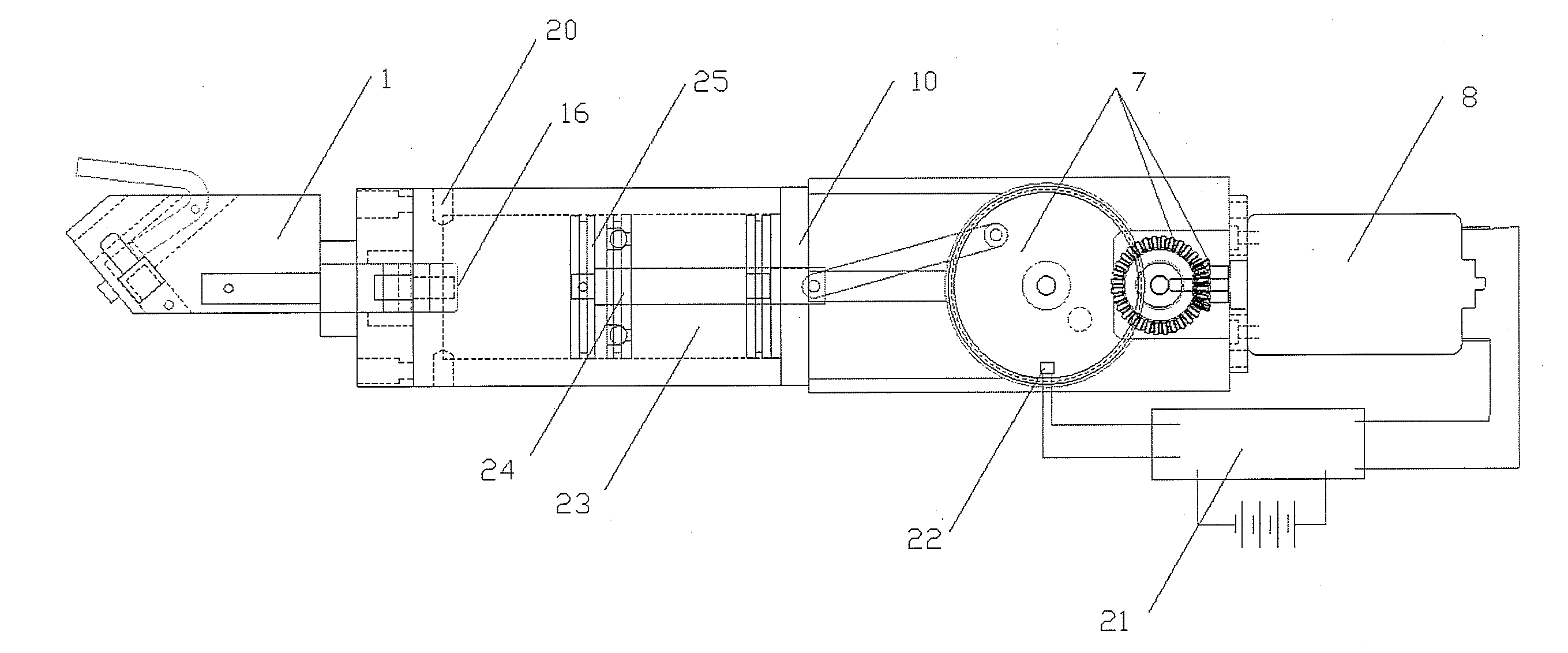
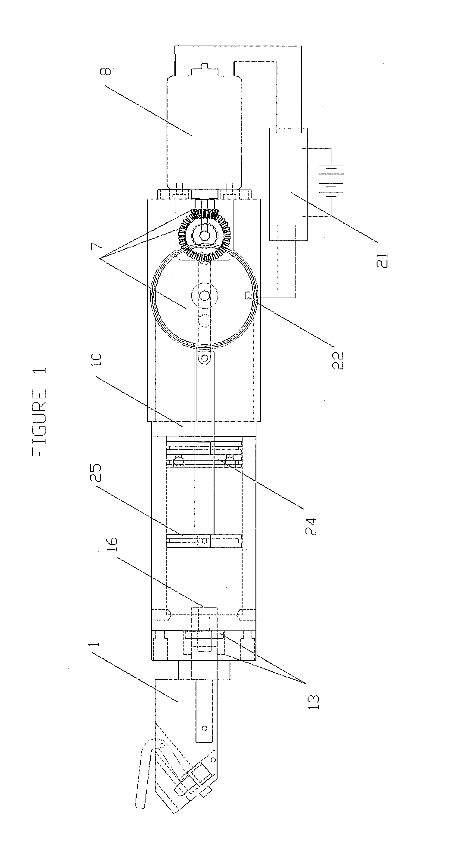
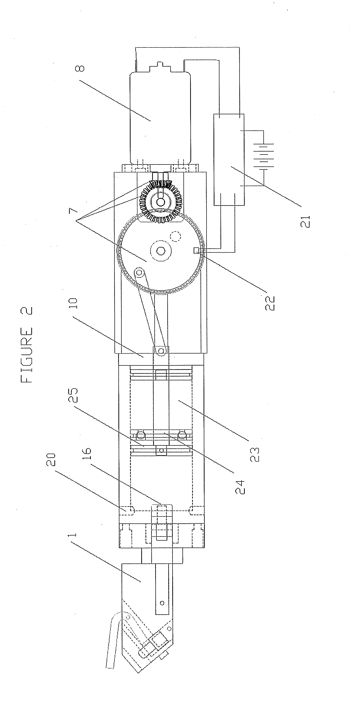
[0009]In view of the foregoing disadvantages of the prior art, an electric motor-driven orthopedic impacting tool configured to include all the advantages of the prior art and to overcome the drawbacks inherent therein is provided. The tool may be used by orthopedic surgeons for orthopedic impacting in hips, knees, shoulders and the like. The tool is capable of holding a broach, chisel, or other end effector and gently tapping the broach, chisel or other end effector into the cavity with controll

Problems solved by technology

Unfortunately, this approach is clumsy and unpredictable as being subject to the skill of the particular physician.
This approach almost will always inevitably result in inaccuracies in the location and configuration of the cavity.
Additionally, the surgeon suffers from fatigue in this approach due to the constant hammering.
Finally, this approach carries with it the risk that the physician will damage bone structure in unintended areas.
This approach is disadvantageous in that it prevents portability of an impacting tool, for instance, because of the presence of a tethering air line, air being exhausted from a tool into the sterile operating field and fatigue of the physician operating the tool.
Further, this approach, as exemplified in U.S. Pat. No. 5,057,112, does n

Method used


Image

  • Electric motor driven tool for orthopedic impacting
  • Electric motor driven tool for orthopedic impacting
  • Electric motor driven tool for orthopedic impacting

Examples


Embodiment Construction

[0036]The best mode for carrying out the present disclosure is presented in terms of its preferred embodiments, herein depicted in the accompanying figures. The preferred embodiments described herein detail for illustrative purposes are subject to many variations. It is understood that various omissions and substitutions of equivalents are contemplated as circumstances may suggest or render expedient, but are intended to cover the application or implementation without departing from the spirit or scope of the present disclosure.

[0037]The terms “a” and “an” herein do not denote a limitation of quantity, but rather denote the presence of at least one of the referenced items.

[0038]The present disclosure provides an electric motor-driven orthopedic impacting tool with controlled percussive impacts. The tool includes the capability to perform single and multiple impacts as well as impacting of variable and varying directions, forces and frequencies. In an embodiment the impact force is a...


PUM

PropertyMeasurementUnit
Fractionaaaaaaaaaa
Pressureaaaaaaaaaa
Sizeaaaaaaaaaa

Abstract

An orthopedic impacting tool comprises a motor, an energy storage means, a striker, and an anvil. The motor stores energy in the energy storage means and then releases it, causing the striker to apply a controlled force on an adapter to create a precise impact for use in a surgical setting. The tool may further comprise a combination anvil and adapter. The tool further allows forward or backward impacting for expanding the size or volume of the opening or for facilitating removal of a broach, implant, or other surgical implement from the opening. An energy adjustment control of the tool allows a surgeon to increase or decrease the impact energy. A light source and hand grips improve ease of operation of the tool.

Description

CROSS-REFERENCE TO RELATED APPLICATIONS[0001]The present application is a continuation of and claims priority under 35 U.S.C. §120 on the pending U.S. patent application Ser. No. 13 / 759,813, filed on Feb. 5, 2013, the disclosure of which is incorporated by reference, which '813 application is a continuation-in-part of and claims priority under 35 U.S.C. §120 on the pending U.S. patent application Ser. Nos. 12 / 980,329, filed on Dec. 29, 2010, and 13 / 466,870 filed on May 8, 2012, as well as under 35 USC §119 on U.S. Provisional Patent Application 61 / 603,320, filed on Feb. 26, 2012, the disclosures of which are incorporated by reference. The present application is also a continuation-in-part of and claims priority under 35 U.S.C. §120 on the pending U.S. patent application Ser. Nos. 12 / 980,329, filed on Dec. 29, 2010, and 13 / 466,870 filed on May 8, 2012, the disclosures of which are incorporated by reference. Additionally, the present application claims priority under 35 USC §119 for p...

Claims


Application Information

Patent Timeline
IPC IPC(8): B25D17/00
CPCB25D17/00A61B17/1626A61B17/1628A61B2019/521A61B17/1668A61B17/92A61B2017/922A61B17/1659A61B17/1604A61B17/16A61B2090/309A61F2/4603A61B2017/00734A61B2017/924B25D11/005B25D11/125B25D2250/195A61B2017/00544B25D11/12B25D17/06B25D2250/221A61F2/46
Inventor PEDICINI, CHRISTOPHER
Owner DEPUY SYNTHES PROD INC
Why Eureka
Try Eureka