Electrical heating device, particularly for a motor vehicle

a technology for electric heating devices and motor vehicles, which is applied in the direction of fluid heaters, air heaters, lighting and heating apparatus, etc., to achieve the effect of generating power

Active Publication Date: 2013-06-27
EBERSPACHER CATEM
View PDF6 Cites 27 Cited by
  • Summary
  • Abstract
  • Description
  • Claims
  • Application Information

AI Technical Summary

Benefits of technology

[0009]The object of the present invention is to specify an electrical heating device that produces effective cooling of a power switch that generates power dissipation while simultaneously protecting the components provided in the connecting housing from environmental influences.
[0011]The sealing element is thereby preferably formed such that the heat sink is retained, within a heat sink insertion opening formed by the connecting housing, such that it is movable in the insertion direction. This mobility of the heat sink within the heat sink insertion opening in the insertion direction has the advantage that the heat sink can evade pressure applied on the sides of the connecting housing within limits, without being pressed out through the heat sink insertion opening, so that the heat sink can be laid against a power transistor under tension. The tension can be produced by means of a separate tension element, for example, by a spring element that acts on the heat sink or on the power switch.
[0015]According to a preferred further development of the present invention, the heat sink has a level contact base on which the power switch can be brought into contact in a thermally conducting manner. This contact base normally extends at a right angle to the insertion opening of the heat sink. The power switch abuts this contact base under tension. As already mentioned, the tension is normally brought about by the sealing provided for the heat sink. As a result of the tension, a countermovement is impressed on the heat sink so that this abuts the power switch constantly under tension and can conduct its power dissipation away in a thermally conducting manner. The mobility of the heat sink within the connecting housing is thereby normally selected such that the heat sink can displace 5 / 10, preferably 7 / 10 mm, in the insertion movement and thereby can equalise thickness tolerances of the power switch without the sealing being lost. Normally used here as a sealing element is a ring-shaped or cylinder-shaped sealing body made of an elastomer, particularly EPDM or silicone. These materials have proven to be particularly suitable for maintaining a tension and sealing even at relatively high temperatures and over a long period of use.
[0022]With a view to increased electrical safety of the electrical heating device, according to a further preferred embodiment it is suggested to place the heat sink on the power switch with an intermediate positioning of an insulating layer. This insulating layer is preferably a ceramic layer. The ceramic layer is thereby preferably formed such that it protrudes over the heat sink circumferentially, as a result of which an increased creep path is created between the power transistor and the heat sink. It is self-evident that the protruding edge of the insulating layer is also normally not supported within the connecting housing, and instead is movable in the insertion direction of the heat sink in order to avoid being damaged when the heat sink is tensed.

Problems solved by technology

Preferably, however, the tension is caused by the compression of an element that causes the sealing.

Method used


Image

  • Electrical heating device, particularly for a motor vehicle
  • Electrical heating device, particularly for a motor vehicle
  • Electrical heating device, particularly for a motor vehicle

Examples


Embodiment Construction

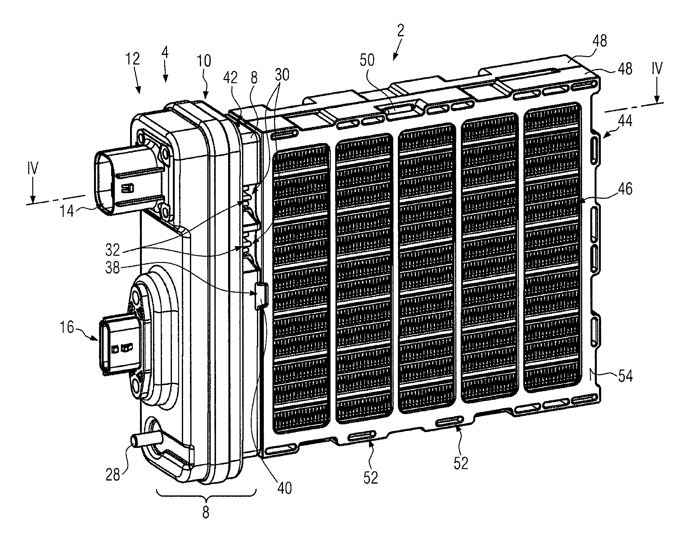
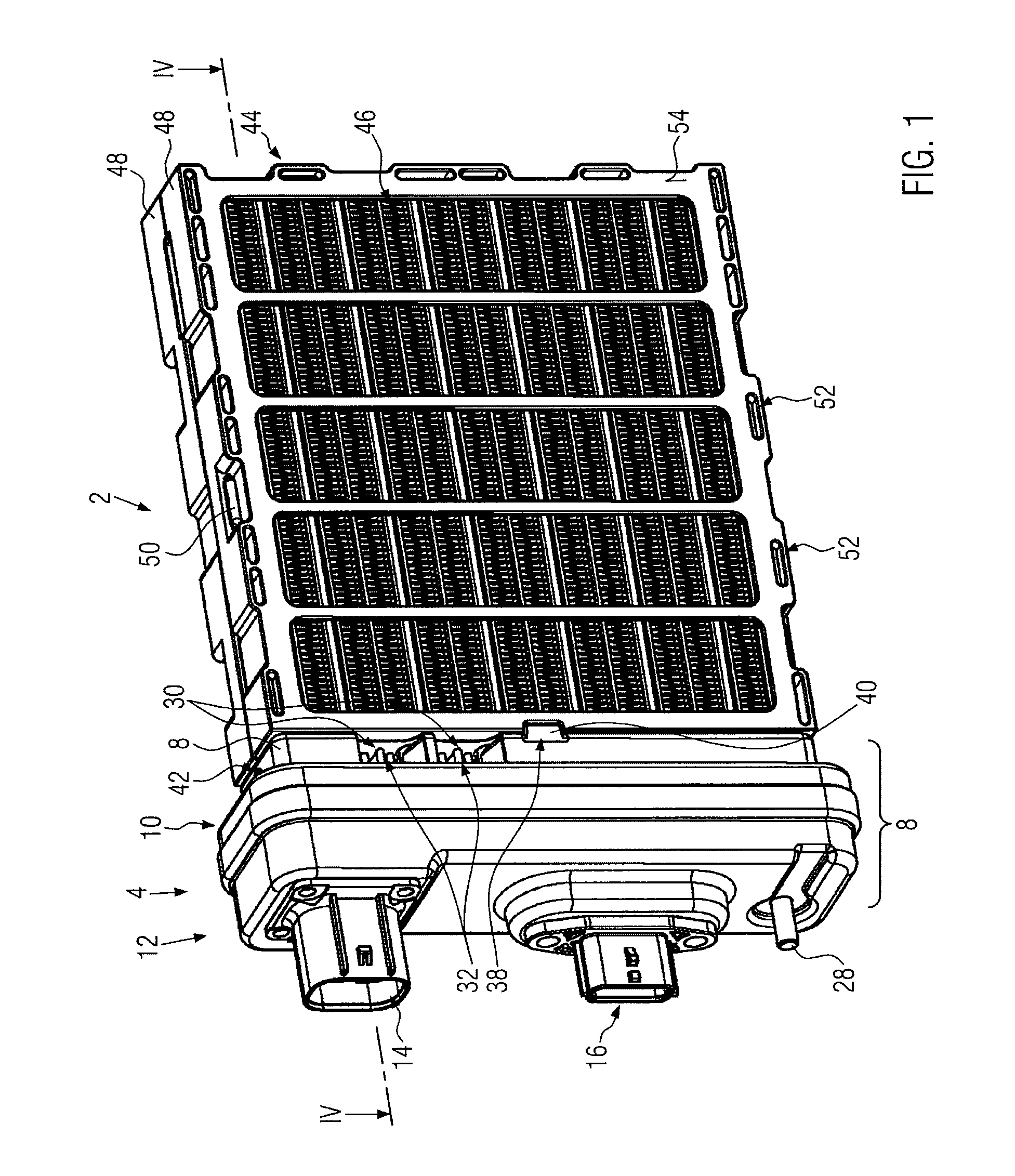
[0043]FIG. 1 illustrates an embodiment of an electrical heating device with a power section labeled with the reference numeral 2 and a control section labeled with the reference numeral 4. The power section 2 and the control section 4 form a constructional unit of the electrical heating device.

[0044]The control section 4 is formed on the outside by a connecting housing 6, which—as shown particularly in the illustration according to FIG. 4—consists of a screening housing 8, which is formed as, for example, a deep-drawn or cast, respectively deep-drawn metal shell, a plastic housing element 10, which is inserted into the metal shell 8 and a housing cover 12. In the joined state the housing cover 12 can grasp over a free flange of the sheet metal cup 8 and be formed of metal so that the interior of the control section 4 is completely screened by a metallic connecting housing 6. The housing cover 12 can however also be formed from plastic.

[0045]The housing cover 12 bears a female plug h...


PUM


Abstract

An electrical heating device for a motor vehicle includes a frame that has openings formed on oppositely situated sides for the passage of a medium to be heated, a layer structure, arranged in the frame, and a connecting housing. The layer structure comprises layers of corrugated-rib elements and heat generating elements, and each heat generating element has at least one PTC element arranged between parallel contact plates. At least one power dissipation generating power switch is provided in the connecting housing. A heat sink lies exposed on the outside of the connecting housing. Improved and adequate cooling of the electrical heating device having the power switch is created as a result of the insertion of the heat sink into the connecting housing in a sealing manner.

Description

BACKGROUND OF THE INVENTION[0001]1. Field of the Invention[0002]The present invention relates to an electrical heating device, particularly to an electrical heating device for a motor vehicle. In particular, the present invention relates to electrical heating devices such as those known, for example, from EP 1 253 808 A1 or EP 0 901 311 A1.[0003]2. Description of the Related Art[0004]In these previously known electrical heating devices, a layer structure is located in a frame that forms, on oppositely situated sides, openings for the passage of a medium to be heated. This layer structure comprises layers of corrugated-rib elements and heat generating elements, whereby the heat generating element has at least one PTC element. This PTC element is located between parallel extending contact plates and is fed current via these contact plates. The electrical heating device furthermore has a connecting housing in which at least one power switch that generates power dissipation is provided ...

Claims


Application Information

Patent Timeline
Patent Type & Authority Applications(United States)
IPC IPC(8): H05B3/02
CPCH05B3/02B60H1/2225B60H2001/2278F24H9/1872F24H3/0441F24H3/0447F24H3/0464F24H3/0435H05B2203/023H05B3/16H05B3/50H05B3/00
Inventor BOHLENDER, FRANZNIEDERER, MICHAELMORGEN, CHRISTIAN
Owner EBERSPACHER CATEM
Why Eureka
Try Eureka