
Radar sensor for motor vehicles

Active Publication Date: 2013-06-27
ROBERT BOSCH GMBH
View PDF11 Cites 0 Cited by
  • Summary
  • Abstract
  • Description
  • Claims
  • Application Information

AI Technical Summary

Benefits of technology

[0011]According to the present invention, these temporally essentially constant components of the DC offset are already compensated by the rough compensation device in the transmit and receive component, so that the only task remaining for the fine compensation device in the evaluation circuit is to compensate the remaining direct voltage components that have a higher temporal variability. Since these variable DC components have a lower amplitude, the compensation is able to be brought about by lower resistor values and thus by means of a correspondin

Problems solved by technology

The DC offset amplified in this manner may cause the baseband signal to no longer fit into the voltage window of the analog-digital converter, so that overmodulation occurs, which leads to distortion errors in the subsequent Fourier transformation.
One disadvantage of this known design of the compensating device is that the resistors in the signal path required for the compensation contribute to an increased n

Method used


Image

  • Radar sensor for motor vehicles
  • Radar sensor for motor vehicles

Examples


Example

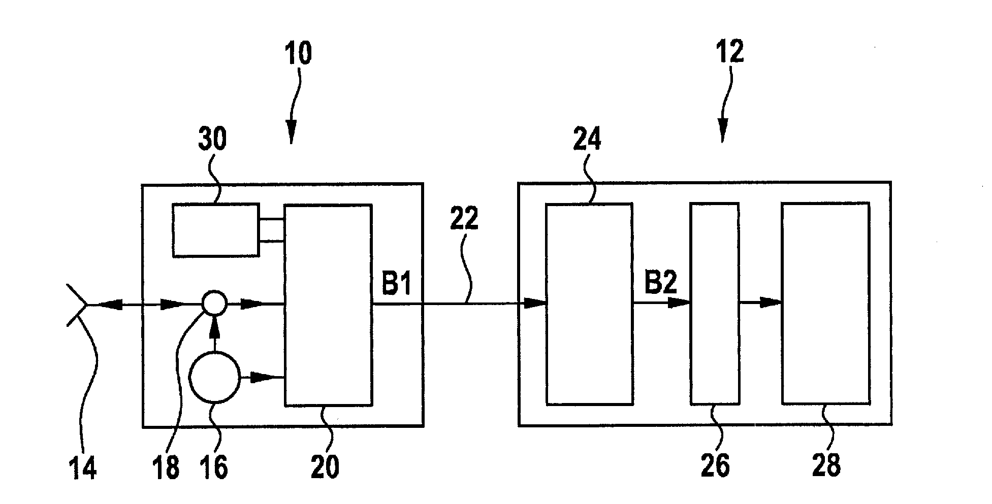
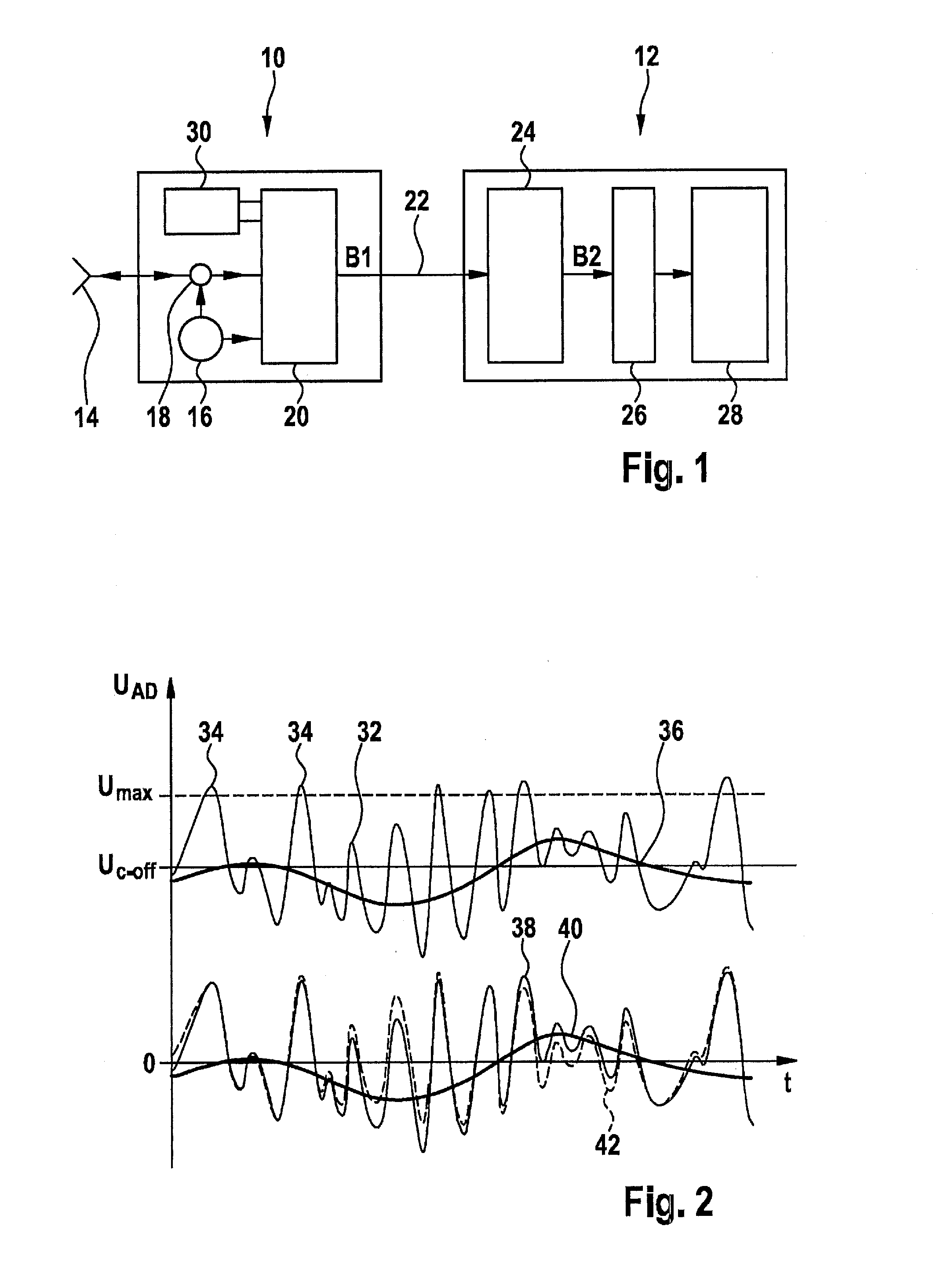
[0014]The radar sensor shown in simplified form in FIG. 1 as a block diagram includes a transmit and receive component 10 in the form of an MMIC (monolithic microwave integrated circuit) and an evaluation circuit 12 in the form of a RADAR-ASIC. An antenna 14, which receives a frequency-modulated radar signal from a local oscillator 16, is connected to transmit and receive component 10, the radar signal then being radiated into the environment by the antenna. The radar echo reflected at objects is then received again by antenna 14, separated in a coupler 18 from the signal supplied by local oscillator 16 and forwarded to an input of a mixer 20. Another input of mixer 20 directly receives the signal (transmitted signal) generated by local oscillator 16. In mixer 20, this transmitted signal is then mixed with the signal received via antenna 14, so that a baseband signal B1 is obtained at the output of the mixer, the frequency of which corresponds to the frequency difference between the...


PUM


Abstract

A radar sensor for motor vehicles includes: a transmit and receive component, which includes a mixer for mixing a transmitted signal with a received signal; an evaluation circuit which is connected to an output of the mixer by a direct voltage coupling device; and a compensation device for compensating a DC offset in the output signal of the mixer, the compensation device being subdivided into a rough compensation device in the transmit and receive component, and a fine compensation device in the evaluation circuit.

Description

BACKGROUND OF THE INVENTION[0001]1. Field of the Invention[0002]The present invention relates to a radar sensor for motor vehicles, having a transmit and receive component which includes a mixer for mixing a transmitted signal with a received signal; it also has an evaluation circuit which is connected to an output of the mixer by a direct voltage coupling device, as well as a compensation device for compensating a DC offset in the output signal of the mixer.[0003]2. Description of the Related Art[0004]Radar sensors in motor vehicles are used for tasks such as locating other vehicles within the scope of distance control systems or collision warning systems. Via an antenna, the transmit and receive component transmits a radar signal, which is modulated in its frequency in ramp-type manner. The radar echo received by the antenna is mixed with a portion of this transmitted signal in the mixer, so that a baseband signal is obtained whose frequency corresponds to the frequency difference...

Claims


Application Information

Patent Timeline
IPC IPC(8): G01S7/03G01S13/931
CPCG01S7/038G01S7/354G01S7/40G01S7/03G01S13/931G01S2007/356G01S13/34G01S7/356
Inventor HIMMELSTOSS, ARMINSTEINBUCH, DIRK
Owner ROBERT BOSCH GMBH
Learn More