Optical Elements with Gradient Structure

Active Publication Date: 2010-12-23
INST FUR NEUE MATERIALIEN GEMEINNUTZIGE GMBH
View PDF26 Cites 7 Cited by
  • Summary
  • Abstract
  • Description
  • Claims
  • Application Information

AI Technical Summary

Benefits of technology

[0010]Since optical gradient structures are nowadays used in many fields having extremely different requirements, for example i

Problems solved by technology

This not only requires the exclusion of oxygen, but severe shrinkage of the material also occurs as a result of the polymerization.
This again leads to high shrinkage in the illuminated regions.
The materials obtained do not display any great advantages over the previously known materials.
However, the thickness of the layers is limited and the material displays high shrinkage because of the free-radical polymerization.
Thus, the systems used are not sensitive enou

Method used


Image

  • Optical Elements with Gradient Structure
  • Optical Elements with Gradient Structure
  • Optical Elements with Gradient Structure

Examples


Example

[0195]FIG. 3 shows an enlarged photograph of the diffraction grating from Example 2 taken using an optical microscope.

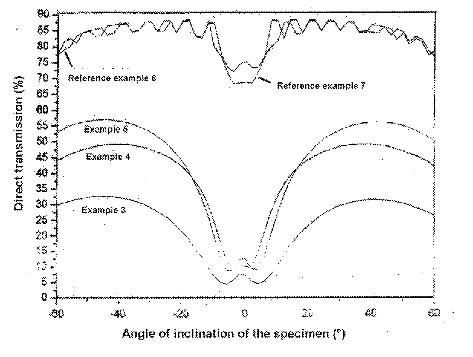
[0196]FIG. 4 shows a measurement of the angle dependence of the direct transmission of the diffuser of Examples 3-5 and Reference Examples 6 and 7 using polychromatic light. The improvement in the optical properties achieved by the process of the invention can clearly be seen.

LIST OF THE REFERENCES CITED

[0197]U.S. Pat. No. 5,552,261

[0198]U.S. Pat. No. 5,529,473

[0199]U.S. Pat. No. 3,658,526

[0200]U.S. Pat. No. 4,959,284

[0201]U.S. Pat. No. 4,942,112

[0202]U.S. Pat. No. 5,013,632

[0203]U.S. Pat. No. 5,098,803

[0204]U.S. Pat. No. 6,482,551

[0205]U.S. Pat. No. 5,453,340

[0206]US 2003 / 0157414

[0207]US 2005 / 0231773

[0208]U.S. Pat. No. 7,022,392

[0209]U.S. Pat. No. 6,969,578

[0210]U.S. Pat. No. 6,268,089

[0211]U.S. Pat. No. 7,163,769

[0212]US 2005 / 0101698

[0213]WO 03 / 058292

[0214]“Ionic Liquids in Synthesis”, P. Wasserscheid, T. Welton, Eds., Wiley-VCH, Weinheim, 2003.

[0215]P. Kubisa, J. ...


PUM

PropertyMeasurementUnit
Percent by massaaaaaaaaaa

Abstract

The invention relates to optical elements with gradient structure, in particular for holographic applications, wherein the gradient structure is formed by a refractive index gradient and a method for production of said optical elements with gradient structure.

Description

FIELD OF THE INVENTION[0001]The invention relates to optical elements having a gradient structure, in particular for holographic applications, wherein the gradient structure is formed by a refractive index gradient, and also a process for producing these optical elements having a gradient structure.PRIOR ART[0002]It is known from the U.S. Pat. Nos. 5,552,261 and 5,529,473 that the diffusion of monomers having an increased or reduced refractive index compared to a surrounding liquid matrix can be used for producing a refractive index gradient. This effect, which is known in the case of polymers as the Colburn-Haines effect, can lead after subsequent polymerization to a product having a refractive index gradient. Such polymers are also referred to as photopolymers.[0003]U.S. Pat. Nos. 3,658,526, 4,959,284, 4,942,112, 5,013,632, 5,098,803 (E.I. Du Pont Nemours) describe the preparation of photopolymers by free-radical polymerization of monomers in a solid medium. This not only requires...

Claims


Application Information

Patent Timeline
IPC IPC(8): G02B5/02G03F7/20G03F7/00G02B3/00B32B7/02
CPCG02B5/00G02B5/32G03F7/001G03F7/0048G03H1/02Y10T428/24942G03H2001/026G03H2001/0264G11B7/24044G11B7/26G03H1/0248
Inventor DE OLIVEIRA, PETER WILLIAMVEITH, MICHAELROGIN, PETERLIN, HECHUNGEERKENS, MARCUS
Owner INST FUR NEUE MATERIALIEN GEMEINNUTZIGE GMBH
Why Eureka
Try Eureka