Focus adjustment apparatus

Inactive Publication Date: 2013-06-27
CANON KK
View PDF4 Cites 3 Cited by
  • Summary
  • Abstract
  • Description
  • Claims
  • Application Information

AI Technical Summary

Benefits of technology

The invention aims to make an AF sensor smaller, cheaper, and more efficient in controlling power consumption. It also aims to minimize the impact of unevenness in shooting speed during continuous shooting, even if there are delays in reading the stored charges.

Problems solved by technology

This is because since it takes a predetermined amount of time to drive the lens and reduce the aperture, if the focus detection operation is not completed while the mirror is down, a finder vanishing time is extended, which makes it difficult for the user to track the object.
Consequently, the frame speed can be uneven.
Especially, when continuously shooting at high speed, since the AF possible time that can maintain the frame speed shortens, the frame speed tends to become uneven.
However, because the focus detection accuracy is guaranteed, the focus detection time lengthens, so that frame speed unevenness tends to occur (FIG. 5).
Further, unevenness in the frame speed also tends to occur when the continuous shooting frame speed has increased because the time that can be spent on the focus detection time shortens.
Consequently, since the focus detection time becomes longer than the current focus detection time, unevenness in the frame speed tends to occur.

Method used


Image

  • Focus adjustment apparatus
  • Focus adjustment apparatus
  • Focus adjustment apparatus

Examples


Embodiment Construction

[0045]Various exemplary embodiments, features, and aspects of the invention will be described in detail below with reference to the drawings.

[0046]Exemplary embodiments according to the present invention will now be described based on the following first and second exemplary embodiments.

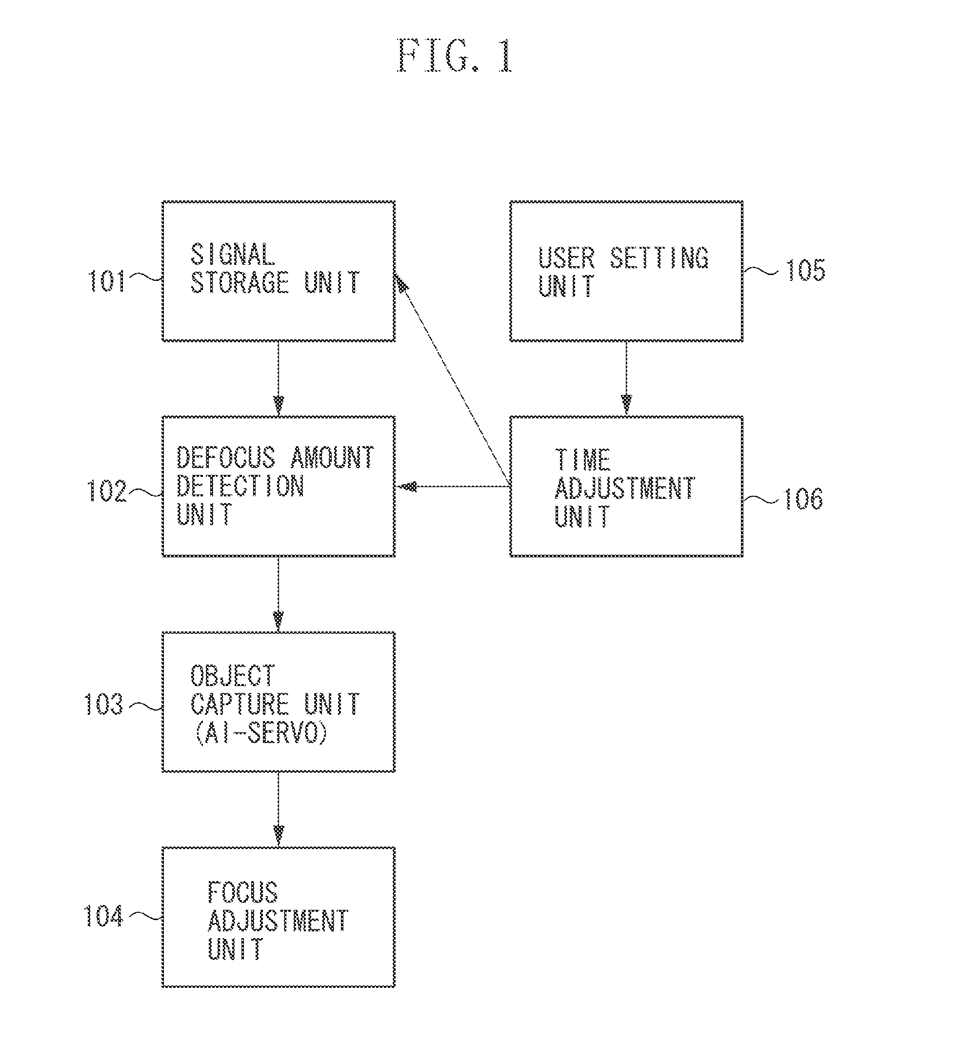
[0047]FIG. 1 is a block diagram illustrating a concept of a focus adjustment apparatus according to a first exemplary embodiment of the present invention. In FIG. 1, the focus adjustment apparatus includes a signal storage unit 101 for storing object image signals in a pair of AF sensors configured of a photoelectric conversion element array and a defocus amount detection unit 102 for detecting a defocus amount from the object image signals. Further, the focus detection apparatus includes a focus adjustment unit 104 for performing focus adjustment of an imaging lens based on the defocus amount, and an object capture unit (AI-servo) 103 that makes the imaging lens continue to focus on a moving object....


PUM


Abstract

In a focus detection apparatus, a sensor includes a first mode for outputting via the signal line when respective stored charges corresponding to the first and the second AF areas have reached the predetermined charge amount, and a second mode for outputting via the signal line when respective stored charges corresponding to the first or the second AF areas have reached the predetermined charge amount.

Description

BACKGROUND OF THE INVENTION1. Field of the Invention[0001]The present invention relates to a focus adjustment apparatus used in a camera, for example.[0002]2. Description of the Related Art[0003]Conventionally, a camera focus detection apparatus has been known that stores object image signals that have passed through an imaging lens in an autofocus (AF) sensor, and detects a defocus amount based on the object image signals stored in the AF sensor.[0004]In such a focus detection apparatus, when continuously focusing on a moving object, a prediction calculation function (AI-servo) moves the imaging lens by performing focus detection for each frame in continuous shooting to predict a future movement position of the object.[0005]As illustrated in FIG. 20, the AI-servo calculates an amount deviating from the object by determining a defocus amount by performing a correlation calculation based on signals stored in the AF sensor. Next, the AI-servo performs a prediction calculation for pred...

Claims


Application Information

Patent Timeline
IPC IPC(8): H04N5/232
CPCH04N5/23212H04N23/67
Inventor SUZUKI, YASUYUKIYOSHIDA, TOMOKAZU
Owner CANON KK
Why Eureka
Try Eureka