Strobe Zoom Device

a technology of strobe zoom and strobe image, which is applied in the direction of lighting device details, lighting and heating apparatus, instruments, etc., can solve the problems of operation sound (noise) that tends to be generated, and achieve the effect of reducing the sound pressure level of zoom operation sound and strobe imaging being performed quietly

Inactive Publication Date: 2013-06-27
NISSIN KOGYO CO LTD +1
View PDF8 Cites 2 Cited by
  • Summary
  • Abstract
  • Description
  • Claims
  • Application Information

AI Technical Summary

Benefits of technology

[0015]In the strobe zoom device according to the present invention, a wire member serves as a female screw member engaging with the feed screw, and the zoom operation sound caused by sliding between the screw groove and the wire member when the feed screw rod is rotated can be absorbed (or deadened) due to absorption of vibration energy by elastic deformation of the wire member. This reduces the sound pressure level of the zoom operation sound and allows strobe imaging to be performed quietly.

Problems solved by technology

In the strobe zoom device of the electrically driven feed screw type, an operation sound (noise) tends to be generated by sliding between the parts that are in threaded engagement when the feed screw rod is rotated during a zoom operation.
Particularly, since the strobe zoom device is typically mounted to a camera and therefore is to be positioned near the head of a person who takes pictures with the camera, the operation sound of the electrically driven feed screw, namely, the zoom operation sound, can be easily heard by the person, and thus, can be disturbing even when the sound pressure level of the operation sound is low.

Method used


Image

  • Strobe Zoom Device
  • Strobe Zoom Device
  • Strobe Zoom Device

Examples


Embodiment Construction

[0022]Now, with reference to FIGS. 1-5, a description will be give of an embodiment of a strobe zoom device according to the present invention.

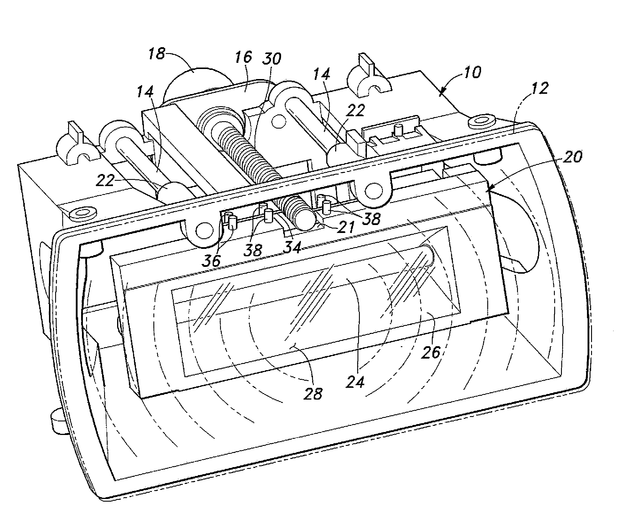
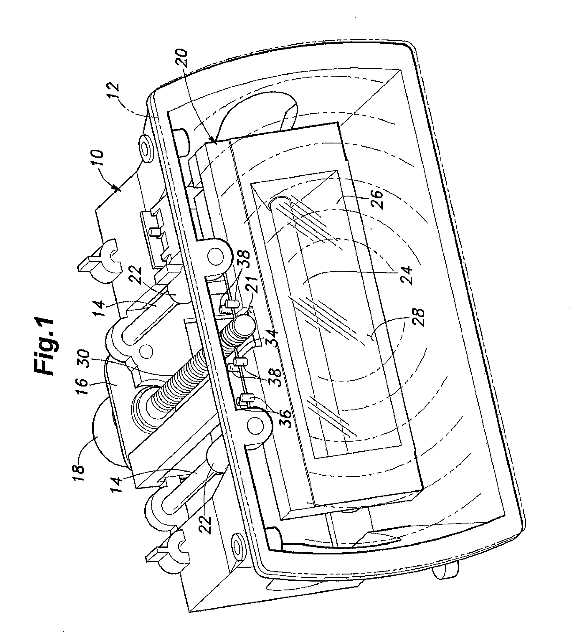
[0023]The strobe zoom device includes a casing 10 made of a synthetic resin and having a parallelepiped box-like shape having a front opening. A planar lens plate 12 constituted of a Fresnel lens is attached to the front part of the casing 10 so as to close the front opening of the casing 10.

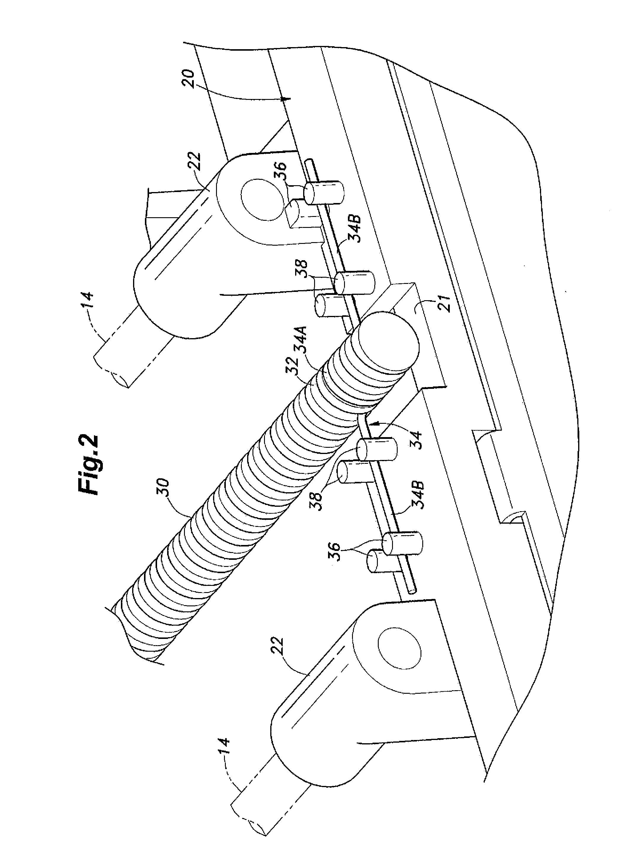
[0024]A pair of guide bars 14 are attached to the casing 10 so as to extend in a fore and aft direction in parallel with each other. A light source box 20 is disposed in the casing 10. The light source box 20 is made of a synthetic resin, and has a parallelepiped box-like shape having a front opening and being smaller in size than the casing 10. The light source box 20 has a pair of sleeve portions 22 formed integrally on top thereof such that the pair of sleeve portions 22 extend in parallel with each other in the fore and aft direction. The sleeve porti...


PUM


Abstract

In a strobe zoom device of an electrically driven feed screw type, to reduce the sound pressure level of zoom operation sound caused by an electrically driven feed screw and to allow strobe imaging to be performed quietly, the electrically driven feed screw for strobe zoom includes: a feed screw rod (30) having a central axis and mounted to a casing (10) so as to be rotatable about the central axis thereof and extend in the fore and aft direction, the feed screw rod including an outer circumferential surface having a screw groove (32) formed thereon; and a wire member (34) attached to a movable body (planar lens plate (12) or a light source box (20)) and including a part wrapped around at least a part of the screw groove (32) so as to be in threaded engagement with the same.

Description

TECHNICAL FIELD[0001]The present invention relates to a strobe zoom device, and particularly to a strobe zoom device of an electrically driven feed screw type.BACKGROUND ART[0002]A strobe zoom device of an electrically driven feed screw type is known in which a light source box disposed in a casing so as to be movable in a fore and aft direction is caused to move in the fore and aft direction by an electrically driven feed screw mechanism to vary a distance along an optical axis between the light source box and a lens disposed in front of the light source box, thereby to vary an illumination angle of strobe light (strobe illumination angle) illuminated onto an object to be imaged.[0003]In the strobe zoom device of the electrically driven feed screw type, a feed screw rod is rotatably mounted to the casing, a female screw member is mounted to the light source box, and a screw thread formed in the female screw member is in threaded engagement with a screw groove formed on the outer ci...

Claims


Application Information

Patent Timeline
Patent Type & Authority Applications(United States)
IPC IPC(8): F21V17/02F21V5/04
CPCG03B15/03F21V17/02F21V5/04G03B15/05G03B2215/0517G03B2215/0528
Inventor SHUM, TAK WAH
Owner NISSIN KOGYO CO LTD
Why Eureka
Try Eureka