Timepiece hand

a timepiece and hand technology, applied in the field of timepiece hands, can solve the problems of difficulty or inability to meet the requirements of prior art techniques, and achieve the effect of significant durability and precise readability

Inactive Publication Date: 2013-06-27
THE SWATCH GRP RES & DEVELONMENT LTD
View PDF10 Cites 8 Cited by
  • Summary
  • Abstract
  • Description
  • Claims
  • Application Information

AI Technical Summary

Benefits of technology

[0010]The aim of the invention is to overcome the disadvantages of the prior art by proposing to provide a metal hand for abrupt acceleration that does not deform during its displacement in order to have precise readability and significant durability.

Problems solved by technology

This then makes it possible to form hands in three dimensions, which the techniques of the prior art do not allow or only with difficulty.

Method used


Image

  • Timepiece hand
  • Timepiece hand
  • Timepiece hand

Examples


Embodiment Construction

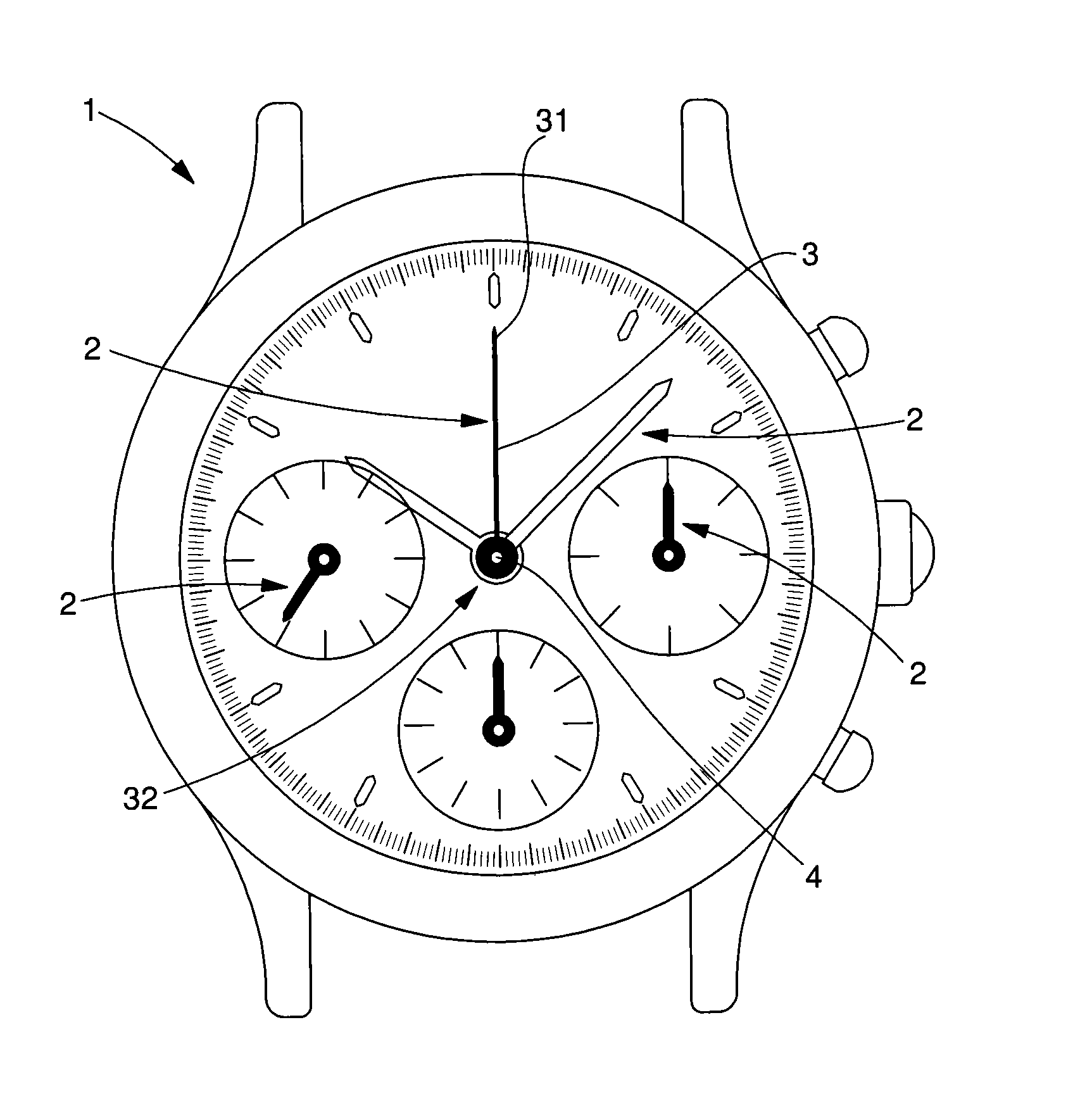
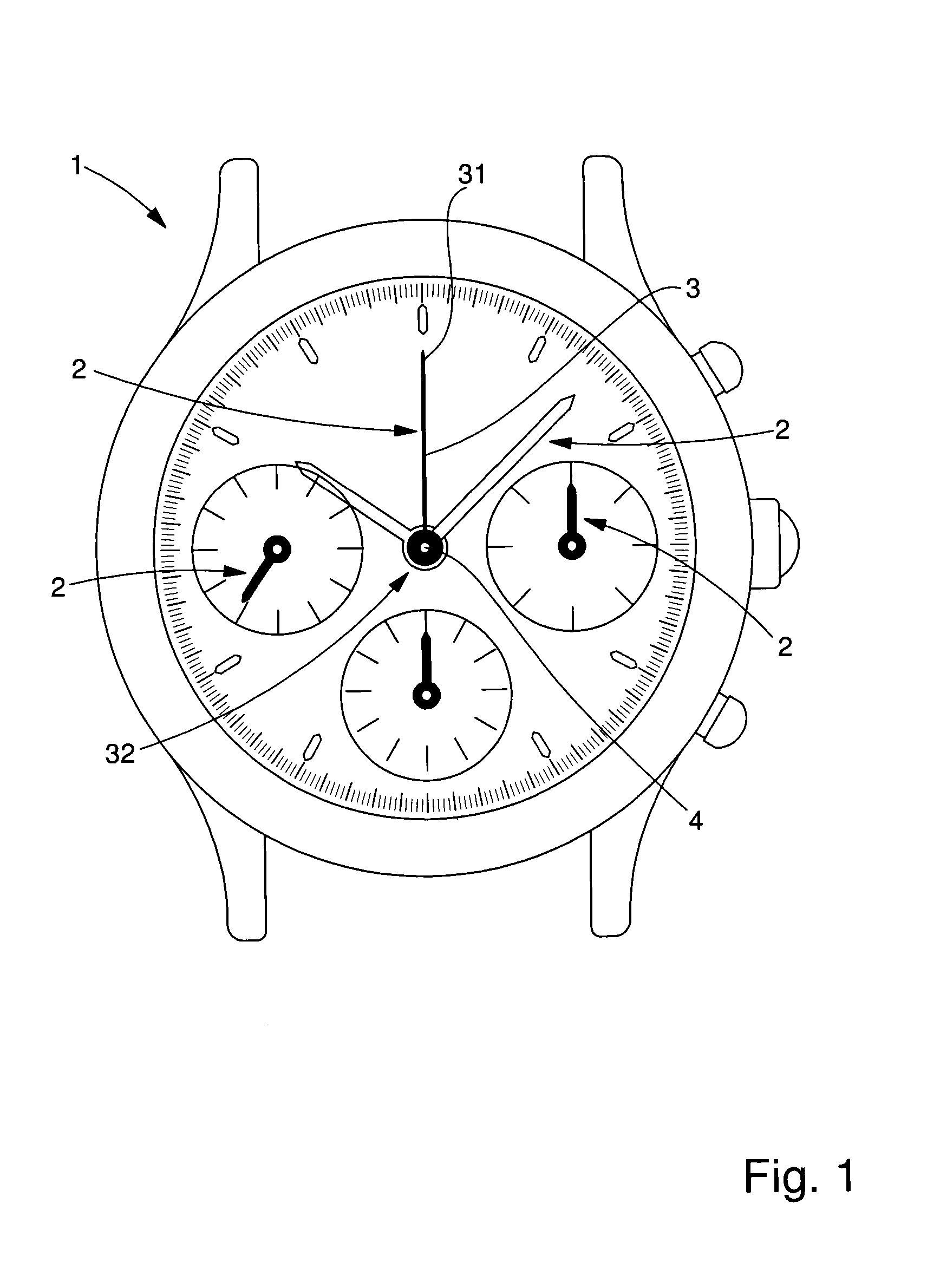
[0041]FIG. 1 shows a timepiece 1 comprising several hands 2 indicating information on the dial of said timepiece. These hands 2 can be hands that indicate the hours, minutes or seconds. They can be driven by continuous or retrograde displacement, wherein said displacement can comprise abrupt accelerations. Abrupt acceleration is understood to mean a sudden acceleration, whether foreseeable or not, that occurs for a limited time and is of very high magnitude, wherein said acceleration follows a displacement of zero, constant or low acceleration. Abrupt accelerations that can be withstood are at minimum 250 000 rad·s−2 and preferably 1.106 rad·s−2. These hands 2 can also be hands of a chronograph or calendar or other. Such a hand 2 shown in FIG. 2 consists of a bar 3 with a length that is much larger than the width of this bar 3, and this width is itself much larger than the thickness. A first end 31 of the bar serves to point at a piece of information. This first end 31 is preferably...


PUM

PropertyMeasurementUnit
Young's modulusaaaaaaaaaa
viscosityaaaaaaaaaa
viscosityaaaaaaaaaa

Abstract

A special hand for abrupt acceleration. The hand is mounted to pivot around a staff so as to be able to indicate an item of information. The hand is made from an at least partially amorphous metal alloy.

Description

[0001]The present invention relates to a timepiece hand, wherein said hand is mounted to pivot around an axis so as to indicate a piece of information.[0002]The technical field of the invention is the technical field of fine mechanics.TECHNOLOGICAL BACKGROUND[0003]It is known that timepieces have hands. These hands consist of a bar with a length that is much larger than the width, which is itself much larger than the thickness. These hands comprise an opening for them to be pressed onto a staff in order to be mounted to pivot. In order to have hands that are fine and strong, it is provided to form them from a crystalline metal such as steel, brass, gold or even silicon or ceramic. These hands can be machined or cut out of a sheet by laser or water jet. They can also be moulded, sintered or formed by growing or depositing material. These hands are then used, for example, to indicate the hours, minutes and seconds, but are also used to perform certain functions such as chronograph fun...

Claims


Application Information

Patent Timeline
Patent Type & Authority Applications(United States)
IPC IPC(8): G04B19/04
CPCB22D17/007B22D25/026G04B19/04G04B19/042G04D3/0046C22C45/10
Inventor HELFER, JEAN-LUCWINKLER, YVES
Owner THE SWATCH GRP RES & DEVELONMENT LTD
Why Eureka
Try Eureka