Toroidal transmission

a transmission and toroidal technology, applied in the direction of gearing, magnetic circuit shape/form/construction, hoisting equipment, etc., can solve the problems of severe durability limit in past toroidal products, and achieve the effect of producing technically superior and economically attractive products and enormous durability benefits

Inactive Publication Date: 2006-04-11
KUEHNLE MANFRED R
View PDF15 Cites 2 Cited by
  • Summary
  • Abstract
  • Description
  • Claims
  • Application Information

AI Technical Summary

Benefits of technology

[0005]It is proposed to introduce nanoparticle technology to manufacture the stators to replace the cutting and milling procedures now in use. Since the hardness of nanoparticles increases with the square of the decrease in particle size, enormous benefits for durability are gained when Hot Isostatic Pressing (HIP) procedures are applied combined with surface nitriding. Further, this manufacturing process involves “zero waste”, and enables the production of technically superior and economically attractive products.

Problems solved by technology

A severe durability limit has existed in past toroidal products caused by the seemingly unavoidable use of needle bearings at the rotor arms.

Method used


Image

  • Toroidal transmission
  • Toroidal transmission
  • Toroidal transmission

Examples


Embodiment Construction

[0022]A description of embodiments of the invention follows.

[0023]To create a high-torque, high-speed, durable-under-heavy-load, advanced XYZ transmission, several inventions became necessary to achieve this heretofore elusive goal.

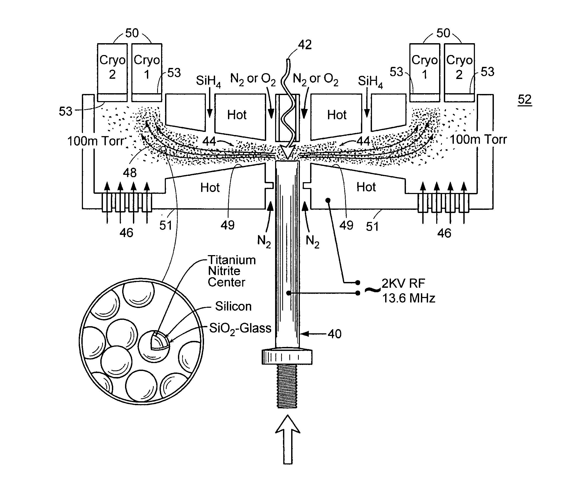
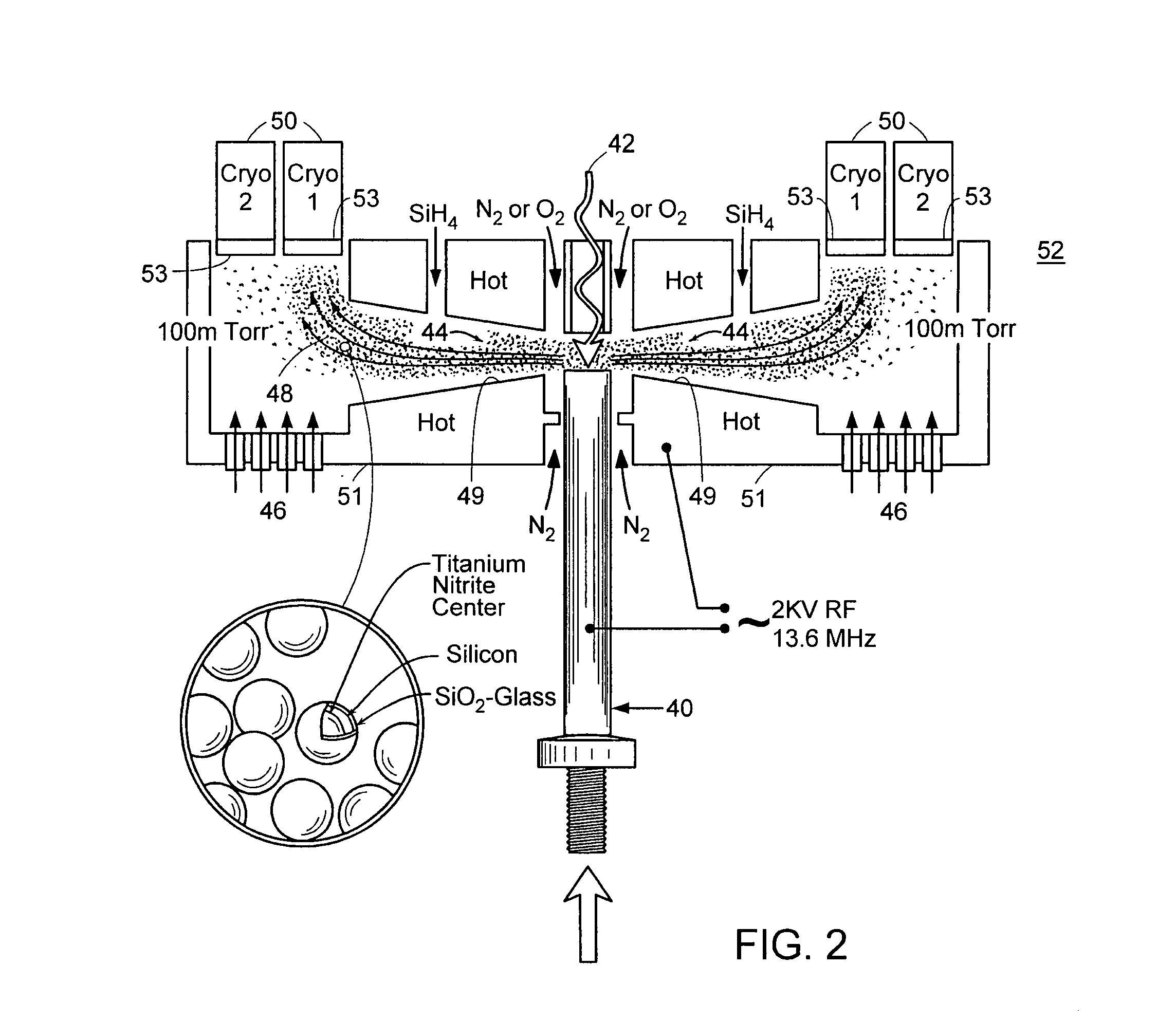
[0024]The first step was to invent a manufacturing process for making monodispersed, cube geometry, metal nanosize particles. FIG. 2 is illustrative of a vessel 52 used to form the nanosize particles. In this new process, metal 40, such as titanium or other suitable material, for example, aluminum, is vaporized inside a protective environment by laser beam 42 or electron beam energy. In a particular embodiment, the laser beam 42 can be generated by a CO2 10 KW laser. Vapor droplets 44 are allowed to escape radially from the vaporization chamber (via slits 49) in a laminar stream into surrounding environment. Due to the geometry of a radial / conical slit in the body member 51, the velocity of the vapor droplets 44 slows down as, simultaneously, the temperat...


PUM

PropertyMeasurementUnit
melting temperatureaaaaaaaaaa
surface areaaaaaaaaaaa

Abstract

A method is provided for optimally engineering a toroidal transmission having a desired input/output ratio to implement the desired ratio of the transmission while meeting the torque and efficiency requirements of the design. Nanoparticle technology is used to manufacture the stator walls to replace the cutting and milling procedures now in use. A novel Mitchell bearing sleeve and its particular hydrodynamic lubrication and cooling method are proposed herein, as well as the introduction of a novel, ultra smooth, amorphous non-oxidizing contact sleeve material used to form the contact sleeve of the drive rollers. A novel self-lubricating system is further provided that includes an oil reservoir disposed within an output shaft of the transmission.

Description

RELATED APPLICATION[0001]This application claims priority to U.S. Application No. 60 / 427,088, filed on Nov. 15, 2002, the entire teachings of which are incorporated herein by reference.BACKGROUND OF THE INVENTION[0002]Over many years, this inventor pursued various implementations of toroidal devices beginning with systems that would have an electronic output (missile nose cone signal transmitters), to very high reduction positioning devices (radar and telescopes), and, lately, to compact, high-torque power XYZ transmissions that can be used in, for example, trucks, automobiles, and marine vessels. Exemplary embodiments of toroidal drive transmissions are disclosed in U.S. Reissue Pat. No. 26,476, issued on Oct. 8, 1968; U.S. Pat. No. 4,297,919, issued on Nov. 3, 1981; U.S. Pat. No. 5,784,923, issued on Jul. 28, 1998; and U.S. Pat. No. 5,863,273, issued on Jan. 26, 1999. The entire teachings of the above documents are incorporated herein by reference.[0003]A transmission of the type ...

Claims


Application Information

Patent Timeline
Patent Type & Authority Patents(United States)
IPC IPC(8): F16H57/08F16H55/32H02K1/12H02K1/22F16H1/30F16H25/06
CPCB22F3/15F16H1/30F16H25/06F16H57/04F16H57/0498B22F9/12Y10T74/19805B22F2998/00B22F2999/00B22F2001/0037B22F1/0018B22F2202/11B22F2202/03B22F2201/10B22F1/0553B22F1/054
Inventor KUEHNLE, MANFRED R.
Owner KUEHNLE MANFRED R
Why Eureka
Try Eureka