Connector-incorporated multi-core optical fiber

Inactive Publication Date: 2013-06-27
SUMITOMO ELECTRIC IND LTD
View PDF6 Cites 3 Cited by
  • Summary
  • Abstract
  • Description
  • Claims
  • Application Information

AI Technical Summary

Benefits of technology

The present invention provides a connector-incorporated multi-core optical fiber that has high optical transmission space density and is easy to bend without getting fractured. The fiber body consists of multiple optical fibers integrated by a coupling material, where the coupling material is removed in an intermediate region of the fiber body to expose parts of the optical fibers. When the fiber body is bent in this intermediate region, the optical fibers are less likely to get fractured, which results in a high bending property and low fracture probability.

Problems solved by technology

Since there is also concern that a leakage loss is caused by optical coupling of propagation modes in the outermost cores with the coating through the cladding, the outermost cores need to be located at some distance from the outer periphery of the cladding.
Since it is difficult to bend the optical fiber with the large cladding diameter in a small bending radius without fracture, such optical fiber is not suitable for optical signal transmission in a module.

Method used


Image

  • Connector-incorporated multi-core optical fiber
  • Connector-incorporated multi-core optical fiber
  • Connector-incorporated multi-core optical fiber

Examples


first embodiment

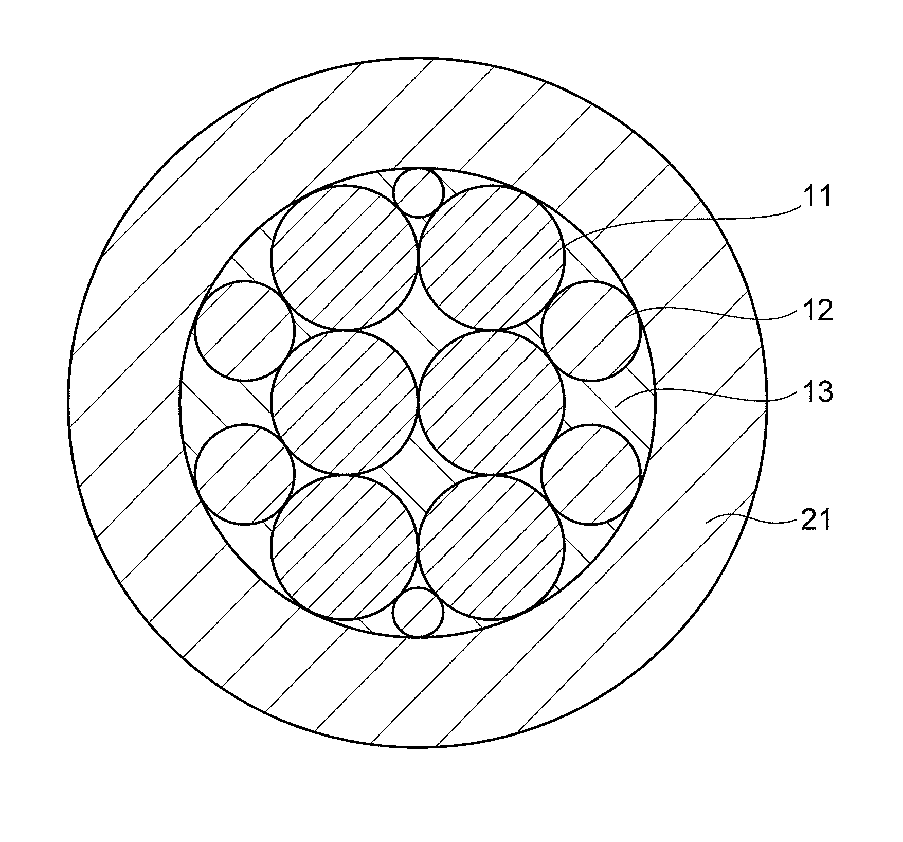
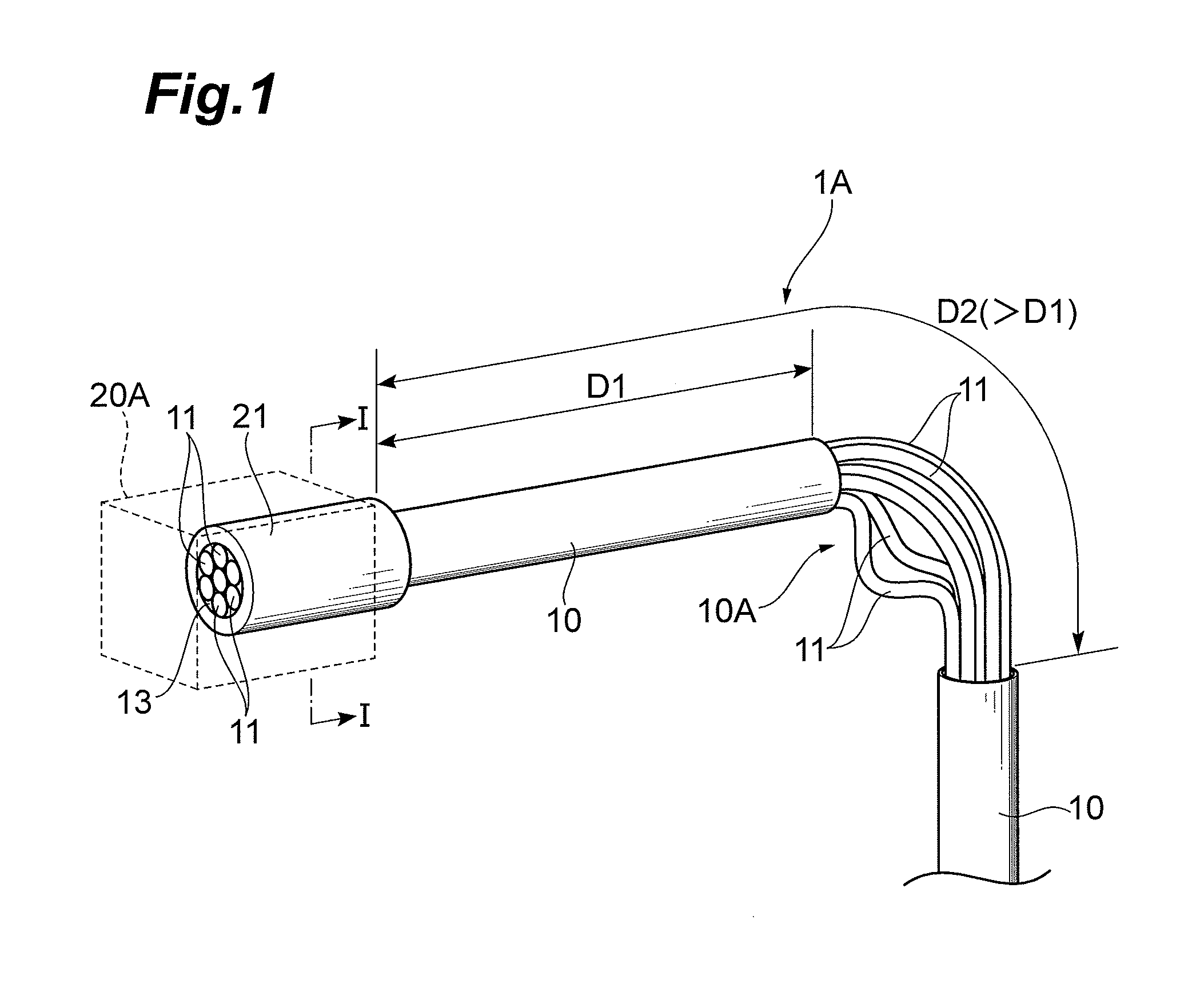
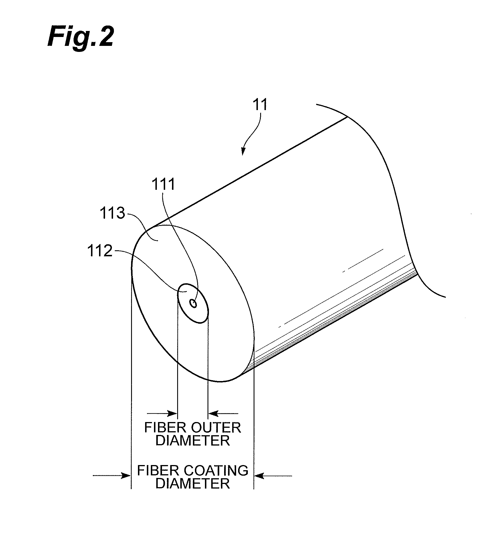
[0022]FIG. 1 is a drawing showing a schematic structure of a connector-incorporated multi-core optical fiber according to the first embodiment. FIG. 2 is a drawing showing a typical structure of an optical fiber applicable to the connector-incorporated multi-core optical fibers according to the first and second embodiments.

[0023]As shown in FIG. 1, the connector-incorporated multi-core optical fiber 1A according to the first embodiment is provided with a fiber body extending along a predetermined axis, and a connector 20A fixed to one end of the fiber body. The fiber body includes a plurality of optical fibers 11, and is composed of bundle sections 10 in which a coupling material 13 encloses each of the optical fibers 11, whereby these optical fibers 11 are integrated by the coupling material 13, and an intermediate region 10A (bent section) located between the bundle sections 10. The coupling material 13 is removed in part from the bent section 10A, whereby each of the optical fibe...

second embodiment

[0040]FIGS. 9A and 9B are drawings showing a schematic structure of the connector-incorporated multi-core optical fiber 1B according to the second embodiment. The typical structure of the optical fiber applicable to the connector-incorporated multi-core optical fiber 1B according to the second embodiment is shown in FIG. 2. FIG. 9B is a sectional view of the connector-incorporated multi-core optical fiber 1B along the line II-II in FIG. 9A.

[0041]The connector-incorporated multi-core optical fiber 1B according to the second embodiment has a ribbon shape in which a plurality of optical fibers 11 are integrated by the coupling material 13 in a state in which the optical fibers 11 are arranged on a common plane. The connector-incorporated multi-core optical fiber 1B is also provided with a fiber body (of ribbon shape) extending along a predetermined axis, and a connector 20B fixed to one end of the fiber body. The fiber body of the ribbon shape also includes a plurality of optical fiber...


PUM


Abstract

The present invention relates to a connector-incorporated multi-core optical fiber with a high optical transmission spatial density and with an excellent bending property. An intermediate region of a fiber body of the connector-incorporated multi-core optical fiber is a region located between bundle sections in which a plurality of optical fibers are integrated by a coupling material, and the coupling material is removed in part from this intermediate region, thereby to expose parts of the respective optical fibers located in the intermediate region.

Description

BACKGROUND OF THE INVENTION[0001]1. Field of the Invention[0002]The present invention relates to a connector-incorporated multi-core optical fiber.[0003]2. Related Background of the Invention[0004]In recent years, data transmission with optical signals is becoming necessary for reduction of consumption power and realization of large capacity signal processing in data communication-related equipment such as blade servers. It necessitates connection of devices in a high spatial density. For improvement in optical transmission spatial density, for example, B. G. Lee, et al., “120-Gb / s 100-m Transmission in a Single Multicore Multimode Fiber Containing Six Cores Interfaced with a Matching VCEL Array,” in IEEE Photonic Society Summer Topical meeting 2010, TuD4.4 (2010) (Non Patent Literature 1) describes an attempt to transmit optical signals through the use of a multimode multi-core optical fiber having a plurality of cores in a common cladding.SUMMARY OF THE INVENTION[0005]The inventor...

Claims


Application Information

Patent Timeline
IPC IPC(8): G02B6/36
CPCG02B6/36G02B6/02042G02B6/443G02B6/4403
Inventor SASAKI, TAKASHI
Owner SUMITOMO ELECTRIC IND LTD
Why Eureka
Try Eureka