Chatter vibration detection method, chatter viberation avoidance method, and machine tool

a technology of vibration detection and avoidance method, applied in the direction of process and machine control, electric programme control, program control, etc., can solve the problems of large amount of data, long data sampling time of about 1 second, and difficulty in immediate detection and avoidance of chatter vibration during machining operations. , to achieve the effect of quick avoidance of that vibration

Active Publication Date: 2013-06-27
MAKINO MILLING MASCH CO LTD
View PDF4 Cites 127 Cited by
  • Summary
  • Abstract
  • Description
  • Claims
  • Application Information

AI Technical Summary

Benefits of technology

[0006]The present invention is made to solve this problem. An object of the present invention is to detect chatter vibration in substantially real time and quickly avoid that vibration.

Problems solved by technology

However, the system described in the above Patent Literature 1 uses Fourier analysis to decide the occurrence of chatter vibration, so a large amount of data is necessary.
For this reason, for example, a long data sampling time of about 1 second is required and immediate detection and avoidance of the occurrence of chatter vibration during a machining operation are difficult.

Method used


Image

  • Chatter vibration detection method, chatter viberation avoidance method, and machine tool
  • Chatter vibration detection method, chatter viberation avoidance method, and machine tool
  • Chatter vibration detection method, chatter viberation avoidance method, and machine tool

Examples


Embodiment Construction

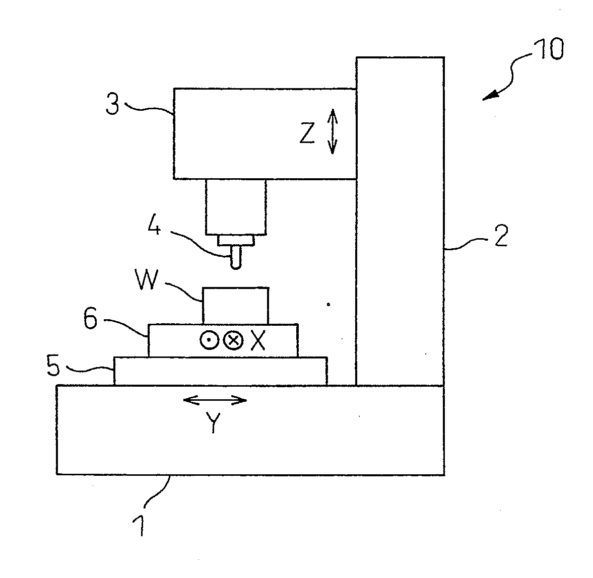
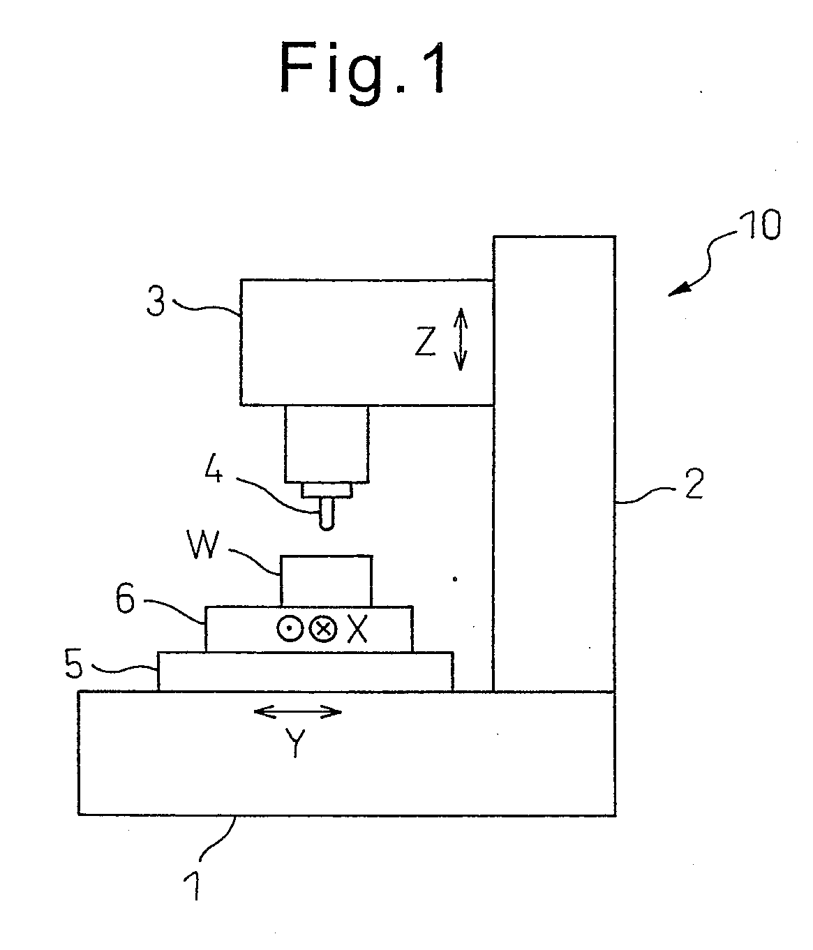
[0020]Below, referring to FIG. 1 to FIG. 8, embodiments of the present invention will be explained. FIG. 1 is a view which shows a general configuration of a machine tool 10 according to an embodiment of the present invention and shows a vertical machining center as an example.

[0021]A column 2 is erected on a bed 1. At the column 2, a spindle head 3 is supported elevatably in the up-down direction (Z-axis direction) through a linear feed mechanism. At the spindle head 3, a cutting tool 4 is attached facing downward via the rotary spindle. The tool 4 is, for example, an end mill which has two cutting edges at symmetric positions in the circumferential direction (first cutting edge 4a and second cutting edge 4b) and is driven to rotate by a spindle motor inside of the spindle head 3. On the bed 1, a saddle 5 is supported movably in the horizontal direction (Y-axis direction) through a linear feed mechanism. On the saddle 5, a table 6 is supported movably in the horizontal direction (X...


PUM

PropertyMeasurementUnit
frequencyaaaaaaaaaa
frequencyaaaaaaaaaa
frequencyaaaaaaaaaa

Abstract

A chatter vibration detection method includes acquiring vibration data of a tool (4) at a time of machining a workpiece at a predetermined sampling period (Δt), calculating an autocorrelation coefficient (Rxx′) corresponding to a time required for a cutting edge (4a, 4b) to contact the workpiece (W) several times based on acquired time series vibration data and calculating a period (Tx) of characteristics of the calculated autocorrelation coefficient (Rxx′), and deciding that chatter vibration occurs when a contact period (T1) at which the cutting edge (4a, 4b) contacts the workpiece (W) is not an integral multiple of the calculated period (Tx).

Description

REFERENCE TO RELATED APPLICATIONS[0001]This application is the national stage application under 35 USC 371 of International Application No. PCT / JP2011 / 060679, filed Apr. 27, 2011, which claims priority from Japanese Patent Application No. 2010-203276, filed Sep. 10, 2010, the entire contents of which are incorporated herein by reference.FIELD OF THE INVENTION[0002]The present invention relates to a chatter vibration detection method which detects the chatter vibration which occurs when machining a workpiece, in particular, chatter vibration which is called “regenerative chatter vibration”, a chatter vibration avoidance method which avoids the chatter vibration, and a machine tool.BACKGROUND OF THE INVENTION[0003]In the past, in a machine tool where a tool attached to a rotary spindle is moved relative to a workpiece so as to work the workpiece, a system designed to suppress the chatter vibration which occurs during the machining operation has been known (for example see Patent Liter...

Claims


Application Information

Patent Timeline
Patent Type & Authority Applications(United States)
IPC IPC(8): B23Q15/08G06F17/00
CPCG05B19/404G05B2219/37434G05B2219/41256Y10T409/304704G06F17/00Y10T409/303808B23Q15/08B23Q15/12B23Q17/12G05B19/416B23Q17/0976
Inventor KONDO, EIJI
Owner MAKINO MILLING MASCH CO LTD
Why Eureka
Try Eureka