Airfoils for wake desensitization and method for fabricating same

a technology of airfoils and wake desensitization, which is applied in the direction of combustion-air/fuel-air treatment, forging/pressing/hammering apparatuses, liquid fuel engines, etc., can solve the problems of increased noise radiated from the turbomachine, non-uniform temperature distribution of the wake flow, and aerodynamic noise and aeromechanical loading generated

Active Publication Date: 2013-06-27
GENERAL ELECTRIC CO
View PDF5 Cites 131 Cited by
  • Summary
  • Abstract
  • Description
  • Claims
  • Application Information

AI Technical Summary

Benefits of technology

[0005]In accordance with another exemplary embodiment, disclosed is an airfoil for use in an engine, said airfoil comprising: a first side and a second side coupled together at a leading edge and a trailing edge; a plurality of first chord sections having a first thickness and defining at least one first chord length and a plurality of second chord sections having a second thickness and defining at least one second chord length, wherein each first chord section of said plurality of first chord sections is defined between each second chord section of said plurality of second chord sections and wherein the first chord length is longer than the second chord length defining a waveform along a leading edge of the airfoil, said leading edge comprises: a plurality of spaced-apart wave-shaped projections each wave-shaped projection of said plurality of wave-shaped projections defines a wave tip and at least one trough portion defined between at least one pair of adjacent spaced-apart wave-shaped projections, wherein adjacent wave-shaped projections define a tip-to-tip distance therebetween, the tip-to-tip distance is within a range of val

Problems solved by technology

In several instances, the wake flow impingement from upstream objects on the downstream airfoils moving relative to each other is a dominant source of aerodynamic noise and aeromechanical loading generated in turbomachinery applications.
In some known engines, the wake flow may contain non-uniform temperature distributions.
A dominant source of aerodynamic noise and aeromechanical loading generated in turbomachinery applications is the interaction of wakes from upstream blade rows o

Method used


Image

  • Airfoils for wake desensitization and method for fabricating same
  • Airfoils for wake desensitization and method for fabricating same
  • Airfoils for wake desensitization and method for fabricating same

Examples


Embodiment Construction

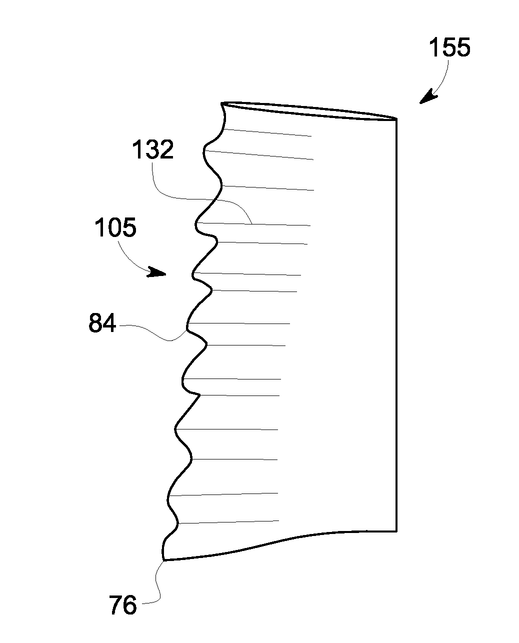
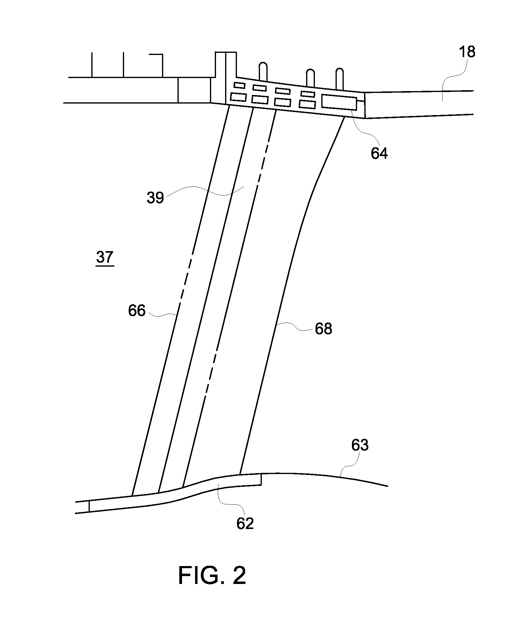
[0022]Disclosed is an apparatus and method for fabricating an airfoil such as, but not limited to, for use in a rotary device. The embodiments described herein are not limiting, but rather are exemplary only. It should be understood that the disclosed embodiments may apply to any type of airfoil or aerodynamic surface, such as, but not limited to, fan blades, rotor blades, stator vanes, ducted fan blades, unducted fan blades, struts, vanes, nacelle inlets, open rotor propulsion systems, wind turbine blades, propellers impellers, diffuser vanes, and / or return channel vanes. More specifically, the disclosed embodiments may apply to any airfoil, or aerodynamic surface, that is subject to impinging wakes and vortices generated upstream of the airfoil.

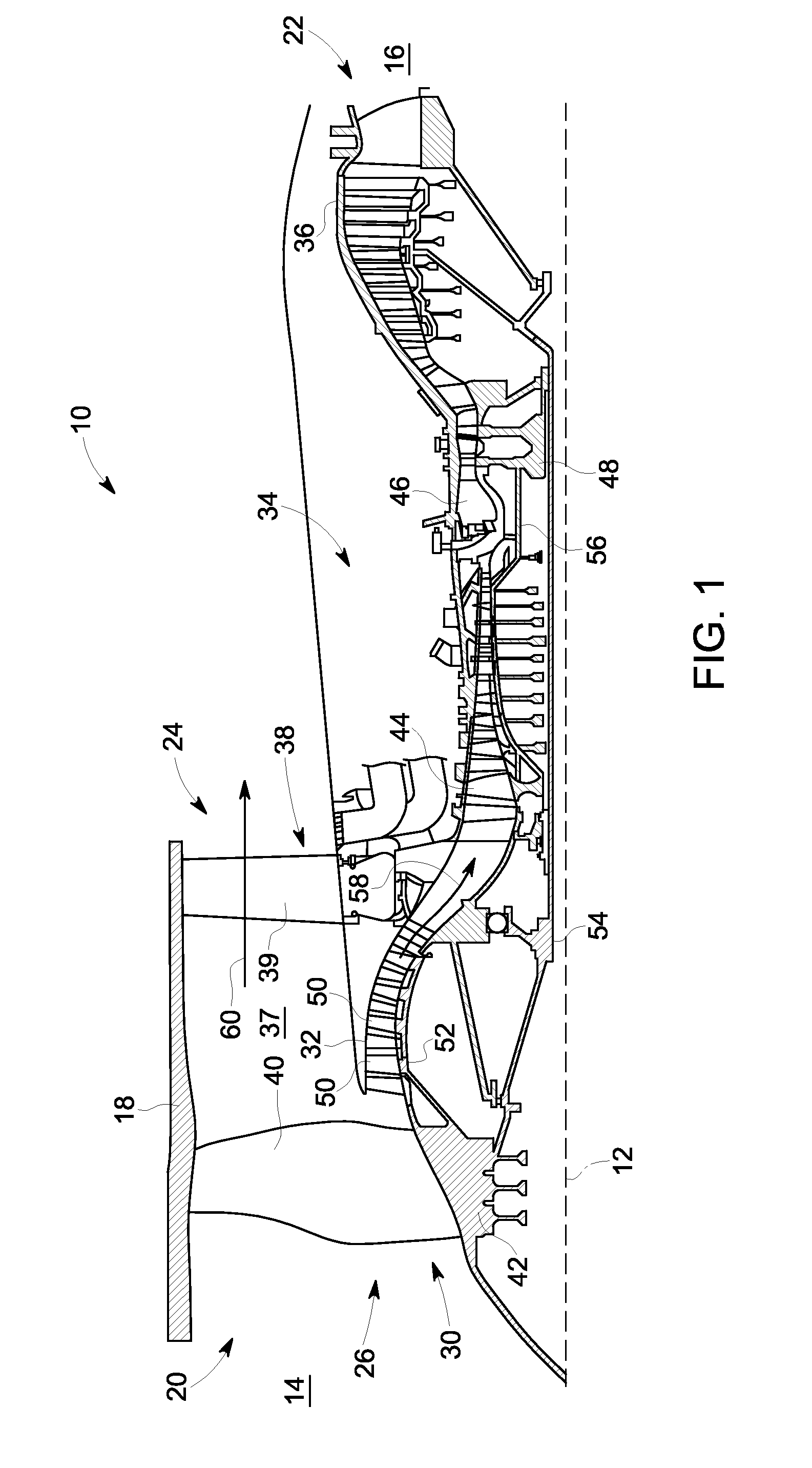
[0023]Although the disclosed embodiments described herein is described in connection with a turbine engine or turbomachinery, it should be apparent to those skilled in the art that, with appropriate modification, the apparatus and methods o...


PUM

PropertyMeasurementUnit
Timeaaaaaaaaaa
Lengthaaaaaaaaaa
Thicknessaaaaaaaaaa

Abstract

An airfoil and method of fabricating an airfoil including a first and a second side coupled together at a leading and a trailing edge and extending there between. The airfoil includes a plurality of first chord sections having a first chord length and extending outward from one of the first side or second side of the airfoil at the leading edge and a plurality of second chord sections having a second chord length and extending outward from the one of the first side or the second side of the airfoil at the leading edge. The leading edge including spaced-apart wave-shaped projections defining a waveform. The configuration defining a three-dimensional crenulated airfoil configured to facilitate desensitization of an airfoil unsteady pressure response to at least one impinging upstream generated wake or vortex by decorrelating spatially and temporally and reducing in amplitude an unsteady pressure caused by interaction of the airfoil with the upstream generated wake or vortex.

Description

BACKGROUND[0001]Embodiments presented herein relate generally to aerodynamic surfaces configured for wake desensitization, and more specifically to configuration of a leading edge on an aerodynamic surface, such as an airfoil, for desensitization of unsteady pressure response to impinging wakes and vortices from upstream.[0002]At least some known machines including aerodynamic surfaces such as, but not limited to, aircraft engines, gas turbine engines, and steam turbine engines, include a plurality of rotating airfoils and stationary airfoils which are subject to impinging wakes and vortices generated from an upstream object, such as an upstream blade row, or an input unsteady airflow. The upstream generated wakes and vortices are channeled downstream where they may impinge on the leading edge of downstream airfoils. In several instances, the wake flow impingement from upstream objects on the downstream airfoils moving relative to each other is a dominant source of aerodynamic noise...

Claims


Application Information

Patent Timeline
IPC IPC(8): F01D5/16B32B3/02F02C7/04B23P15/00F01D9/02F01D5/14
CPCF05B2250/611Y10T29/49336F04D29/324F01D5/141F01D9/041F03D1/0633F05D2220/36F05D2240/121F05D2240/303F05D2250/184Y02T50/671Y02T50/673Y02E10/721Y10T29/49323Y10T29/49321Y10T29/49332Y10T29/49316F05D2250/611Y02E10/72Y02T50/60Y10T137/0536
Inventor WOOD, TREVOR HOWARDRAMAKRISHNAN, KISHOREPALIATH, UMESH
Owner GENERAL ELECTRIC CO
Why Eureka
Try Eureka