Neurostimulation methods and systems

Active Publication Date: 2013-06-27
THE BOARD OF TRUSTEES OF THE LELAND STANFORD JUNIOR UNIV +1
View PDF2 Cites 66 Cited by
  • Summary
  • Abstract
  • Description
  • Claims
  • Application Information

AI Technical Summary

Benefits of technology

The patent text describes a stimulation component that can be used to treat certain conditions by stimulating nerves in the body. The component includes a connector, electrodes, a lead, and a strain relief mechanism to prevent damage to the electrodes. The electrodes are designed to maintain their position when the body is in different positions, such as sitting upright or lieing down. The stimulation can be targeted to specific nerves without stimulating others. This invention can help improve the safety and effectiveness of stimulation therapy for certain medical purposes.

Problems solved by technology

Accordingly, electrical stimulation intended to manage / control one condition (for example, pain) often results in the inadvertent interference with nerve transmission pathways in adjacent nervous tissue (for example, motor nerves).
Moreover, these and other conventional, non-specific stimulation systems also apply stimulation energy to the spinal cord and to other neural tissue beyond the intended stimulation targets.
Moreover, larger epidural electrode arrays may alter cerebral spinal fluid (CSF) flow thus further altering local neural excitability states.
Another challenge confronting conventional neuro stimulation systems is that since epidural electrodes must apply energy across a wide variety of tissues and fluids (i.e., CSF fluid amount varies along the spine as does pia matter thickness) the amount of stimulation energy needed to provide the desired amount of neurostimulation is difficult to precisely control.
However, as applied stimulation energy increases so too increases the likelihood of deleterious damage or stimulation of surrounding tissue, structures or neural pathways.
An improperly defined electric field may not only be ineffective in controlling / managing the desired condition(s) but may also inadvertently interfere with the proper neural pathways of adjacent spinal nervous tissue.

Method used


Image

  • Neurostimulation methods and systems
  • Neurostimulation methods and systems
  • Neurostimulation methods and systems

Examples


Embodiment Construction

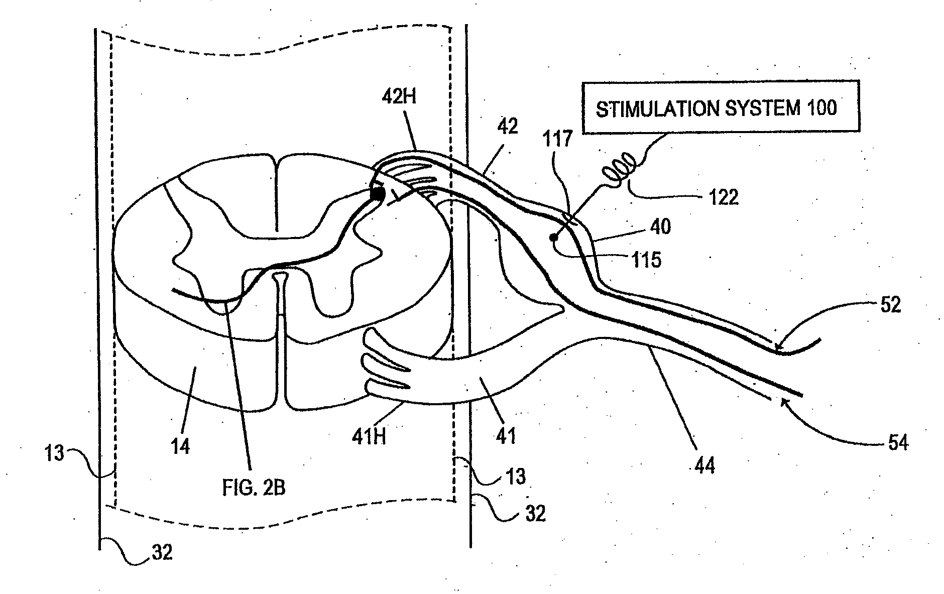
[0079]Embodiments of the present invention provide novel stimulation systems and methods that enable direct and specific neurostimulation techniques. For example, there is provided a method of stimulating a nerve root ganglion comprising implanting an electrode into the nerve root ganglion and activating the electrode to stimulate the nerve root ganglion. As discussed in greater detail below, the nerve root ganglion may be a dorsal root ganglion in some embodiments while in other embodiments the nerve root ganglion may be a nerve root ganglion in the sympathetic nervous system or other ganglion or tissue. In some embodiments, implanting the electrode includes forming an opening in the epinurium of the root ganglion and passing the electrode through the opening and into the interior space or interfascicular space of the ganglion.

[0080]In other embodiments, portions of an electrode body pass completely through a ganglion while maintaining an active electrode area appropriately positio...


PUM


Abstract

Some embodiments of the present invention provide stimulation systems and components for selective stimulation and / or neuromodulation of one or more dorsal root ganglia through implantation of an electrode on, in or around a dorsal root ganglia. Some other embodiments of the present invention provide methods for selective neurostimulation of one or more dorsal root ganglia as well as techniques for applying neurostimulation to the spinal cord. Still other embodiments of the present invention provide stimulation systems and components for selective stimulation and / or neuromodulation of one or more dorsal root ganglia through implantation of an electrode on, in or around a dorsal root ganglia in combination with a pharmacological agent.

Description

CROSS-REFERENCE TO RELATED APPLICATIONS[0001]This application is a continuation-in-part of U.S. patent application Ser. No. 12 / 051,770, filed Mar. 19, 2008, titled “NEUROSTIMULATION SYSTEM,” Publication No. US-2008-0167698-A1, which is a continuation of U.S. patent application Ser. No. 11 / 221,576, filed Sep. 7, 2005, titled “NEUROSTIMULATION SYSTEM,” Publication No. US-2006-0052836-A1, now abandoned, which claims the benefit of U.S. Provisional Patent Application No. 60 / 608,357, filed Sep. 8, 2004, titled “NEUROSTIMULATION SYSTEMS AND METHODS,” each of which is incorporated herein by reference in its entirety.INCORPORATION BY REFERENCE[0002]All publications and patent applications mentioned in this specification are herein incorporated by reference to the same extent as if each individual publication or patent application was specifically and individually indicated to be incorporated by reference.FIELD[0003]The present invention relates to neurostimulation methods and systems that e...

Claims


Application Information

Patent Timeline
IPC IPC(8): A61N1/36
CPCA61B5/01A61B5/4836A61N1/36071A61N1/0551A61N1/36164A61N1/0568A61N1/36017A61N1/36021A61N1/0558
Inventor KIM, DANIEL H.IMRAN, MIR A.KRAMER, JEFFERY M.
Owner THE BOARD OF TRUSTEES OF THE LELAND STANFORD JUNIOR UNIV
Why Eureka
Try Eureka