
Methods and system for displaying pedigree charts on a touch device

a touchscreen device and pedigree chart technology, applied in the field of methods and systems for displaying genealogical records on the touchscreen device, can solve the problem of limited amount of information

Active Publication Date: 2013-06-27
ANCESTRY COM OPERATIONS
View PDF26 Cites 21 Cited by
  • Summary
  • Abstract
  • Description
  • Claims
  • Application Information

AI Technical Summary

Benefits of technology

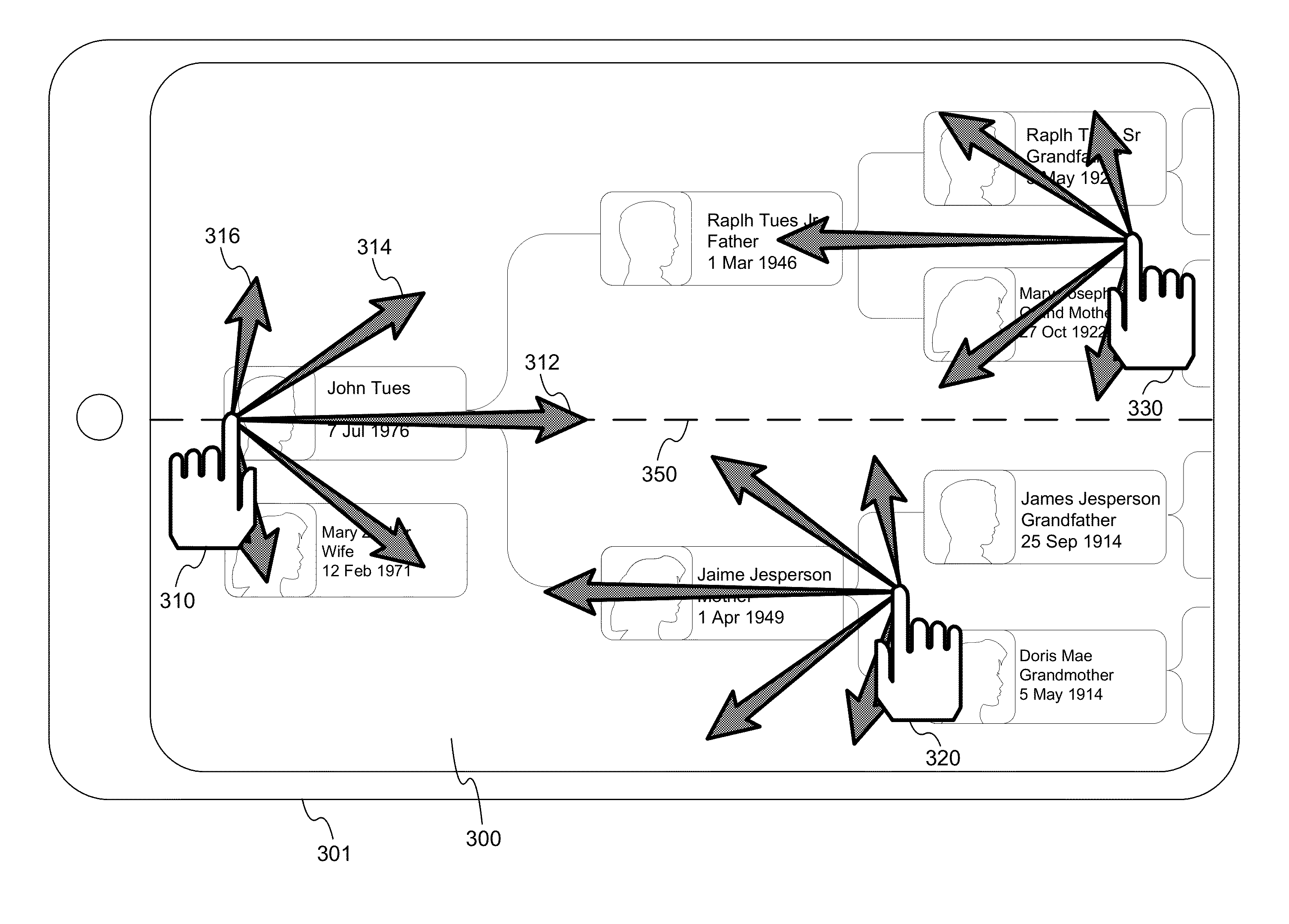
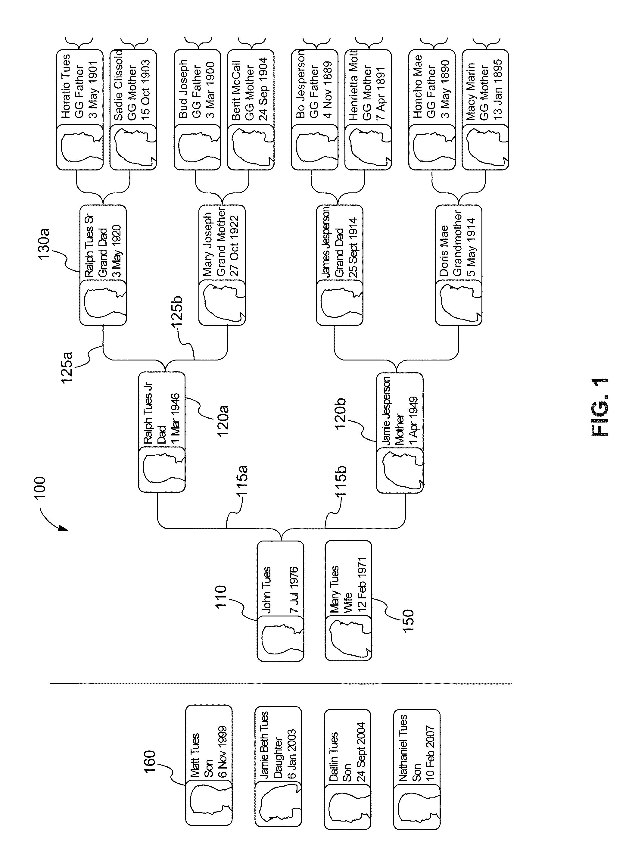
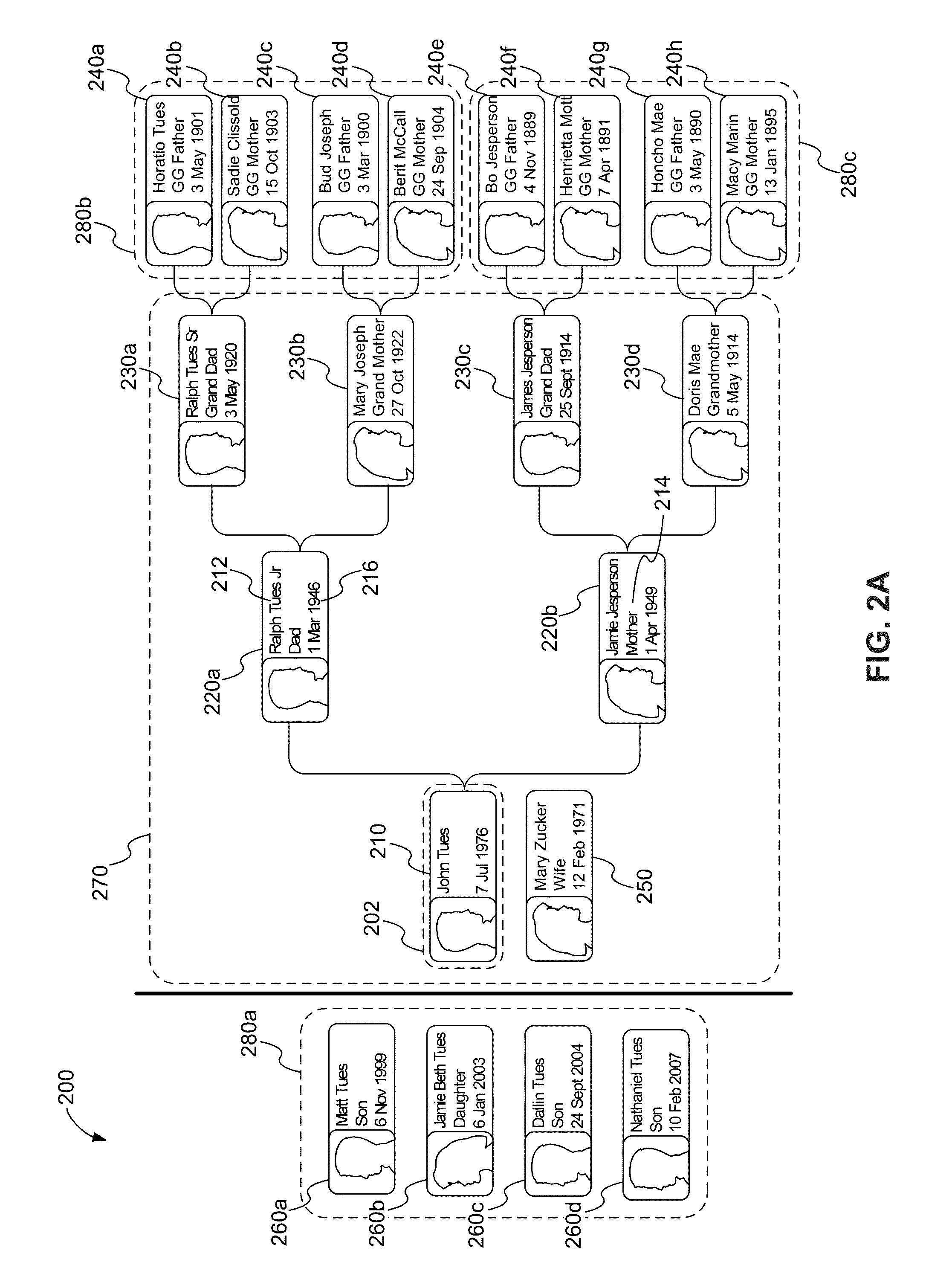
This patent describes a computer program that allows users to view and access genealous records. The program includes instructions that allow users to select a specific gene guerra record and view information related to it. The program also displays icons on a touch screen that users can interact with to view additional information about their ancestors. The directions of the icon movements on the screen determine the direction in which the user's ancestors are linked. This makes it easy for users to access and view the information they need about their ancestors.

Problems solved by technology

However, only a limited amount of this information may be displayed on a touch-screen device at one time

Method used


Image

  • Methods and system for displaying pedigree charts on a touch device
  • Methods and system for displaying pedigree charts on a touch device
  • Methods and system for displaying pedigree charts on a touch device

Examples


Embodiment Construction

[0021]While various aspects and features of certain embodiments have been summarized above, the following detailed description illustrates a few exemplary embodiments in further detail to enable one of skill in the art to practice such embodiments. In the following description, for the purposes of explanation, numerous specific details are set forth in order to provide a thorough understanding of the described embodiments. It will be apparent, however, to one skilled in the art that other embodiments of the present invention may be practiced without some of these specific details. In other instances, well-known structures and devices are shown in block diagram form. Several embodiments are described herein, and while various features are ascribed to different embodiments, it should be appreciated that the features described with respect to one embodiment may be incorporated into other embodiments as well. By the same token, however, no single feature or features of any described emb...


PUM


Abstract

The present invention discloses an air fan turbine positioned horizontally or vertically in close proximity to the exhaust fan system of air handler systems. These turbine units catch the exhausted air flow from the exhaust ports of these air handler units to drive the turbine blades which are attached to a generator. As the propellor blades spin, they generate electricity. Thus, the man made air flow known as exhaust from the air handler systems is used to produce electricity. This invention not only uses man made air flow, but also repositions the air turbine 90° from a horizontal position to a vertical position to receive wind air from the atmosphere. When the air handler unit is turned off, a signal is sent to mechanically move the air turbine to the vertical position to redirect itself to then catch natural wind airflow on both roof top and ground mounted units.

Description

CROSS-REFERENCES TO RELATED APPLICATIONS[0001]This application is related to co-pending U.S. patent application Ser. No. 13 / 035,845 filed on Feb. 25, 2011 entitled “ANCESTOR-TO-ANCESTOR RELATIONSHIP LINKING METHODS AND SYSTEMS” which is incorporated herein by reference. This application is also related to co-pending U.S. patent application Ser. No. 13 / 035,816 filed on Feb. 25, 2011 entitled “METHODS AND SYSTEMS FOR IMPLEMENTING ANCESTRAL RELATIONSHIP GRAPHICAL INTERFACE” which is also incorporated herein by reference.TECHNICAL FIELD[0002]The present invention relates generally to methods and systems for displaying genealogical records on a touch-screen device and more specifically to methods and systems for transitioning between displayed records and / or between one or more views.BACKGROUND OF THE INVENTION[0003]Interest in genealogical research has grown tremendously over the last century and has become a popular hobby among all age groups. Much of the excitement surrounding genealo...

Claims


Application Information

Patent Timeline
Patent Type & Authority Applications(United States)
IPC IPC(8): G06F3/048G16B45/00
CPCG06F3/0488G06F3/0485G06F3/0486G06Q10/06G06F2203/04803G06F19/26G06F17/30961G06Q10/00G06F16/9027G16B45/00
Inventor MANGUM, GARYBRYANT, JOSH
Owner ANCESTRY COM OPERATIONS
Learn More