

Tumble dryer with automatic fire extinguishing system
- Summary
- Abstract
- Description
- Claims
- Application Information
AI Technical Summary
Benefits of technology
Problems solved by technology
Method used
Image

Examples
Embodiment Construction
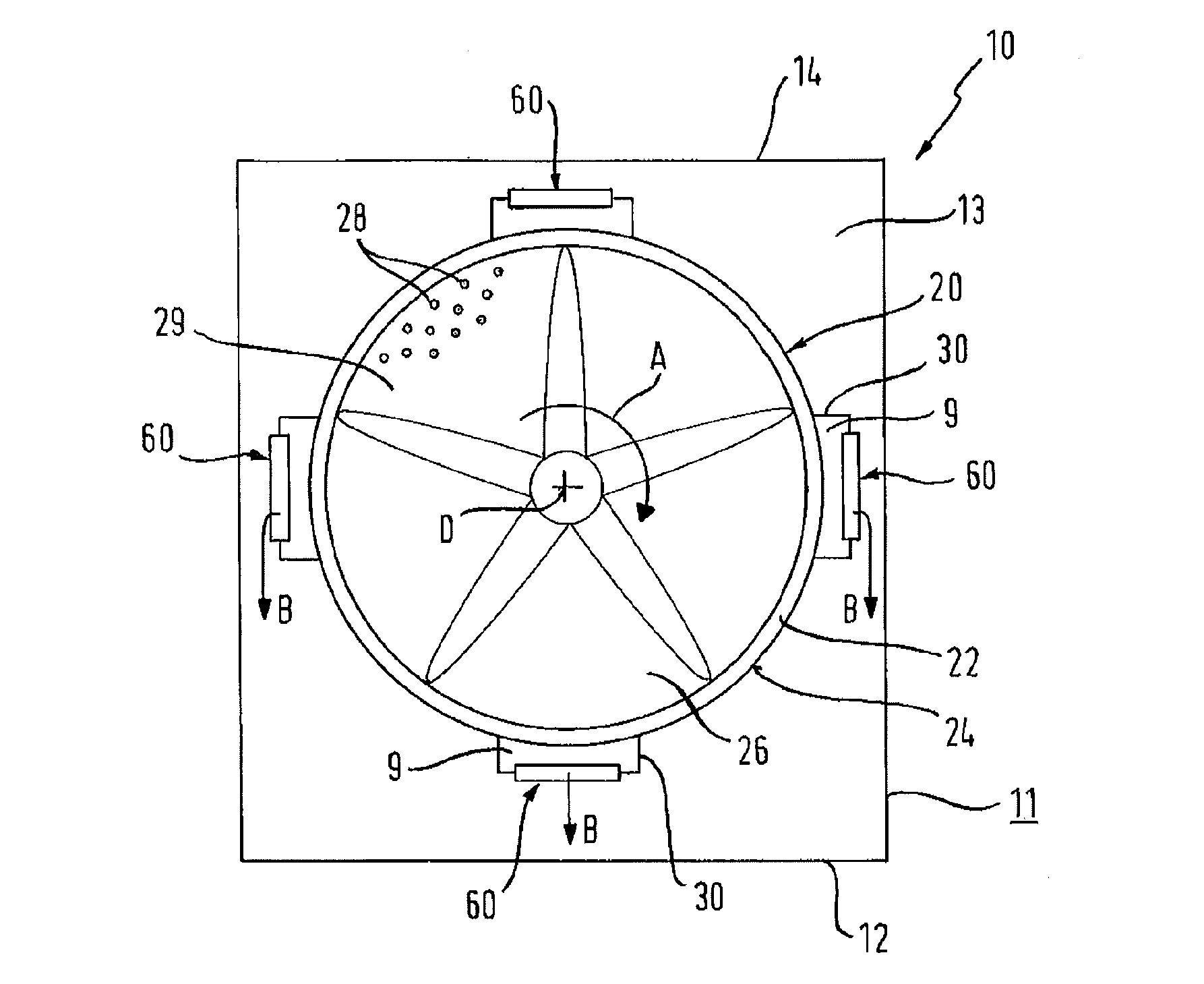
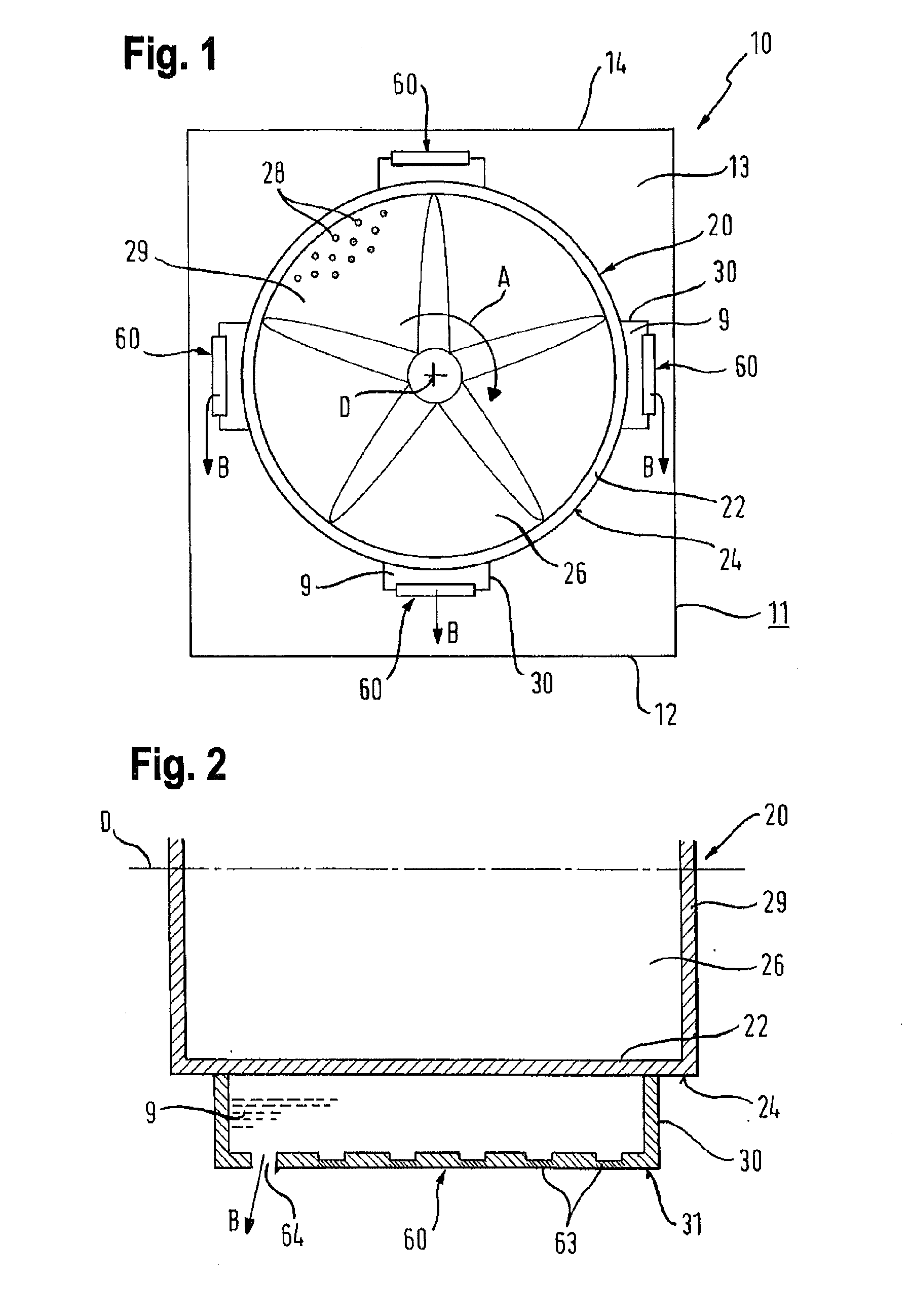
[0028]FIG. 1 shows a schematic diagram of a first embodiment of the tumble dryer 10. Present in a housing 11, which is delimited at the bottom by a base plate 12 and at the top by a worktop 14, is a drum 20, into which the laundry to be dried is introduced. The tumble dryer 10 and the drum 20 present therein are shown in a rear view, in which the rear wall 29 of the drum 20 can be seen, having a large number of small openings 28 for the passage of air. The drum 20 can be rotated about a rotation axis D running perpendicular to the plane of the drawing according to FIG. 1, as shown by an arrow A.
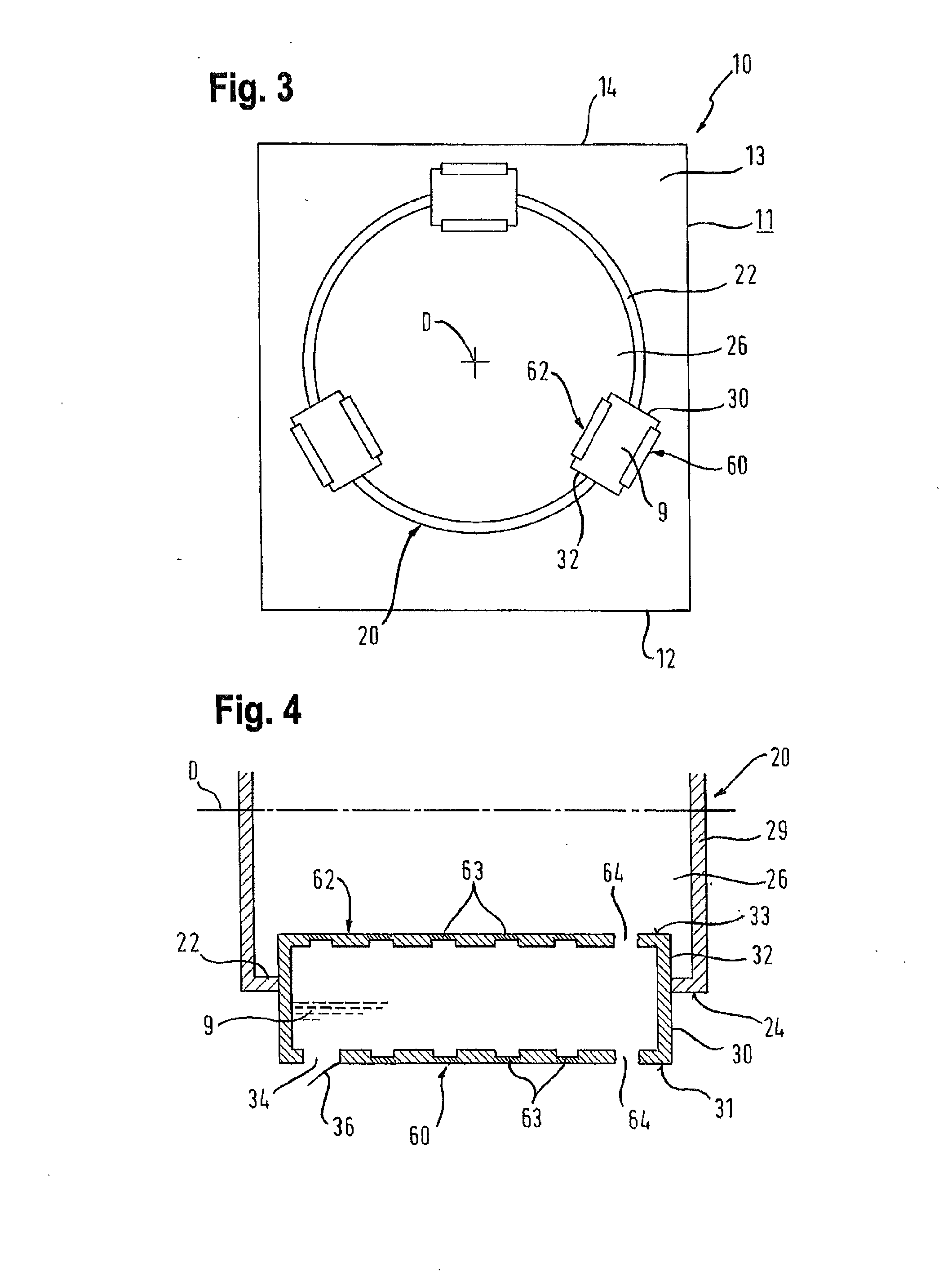
[0029]Positioned on the outer face 24 of the drum casing 22 in this embodiment at an angular distance of 90° are four containers 30 containing an extinguishing agent 9. Each container 30 has a temperature-activated release facility 60, which is embodied so that after being activated at a certain temperature, as produced in a fire, it releases the extinguishing agent 9 automatically into a spa...
PUM
 Abstract
Description
Claims
Application Information