Impact load monitoring system and impact load monitoring method for wind turbine for wind power generation

a monitoring system and wind turbine technology, applied in the direction of engine testing, structural/machine measurement, instruments, etc., can solve problems such as abnormalities

Active Publication Date: 2013-07-04
MITSUBISHI HEAVY IND LTD
View PDF8 Cites 19 Cited by
  • Summary
  • Abstract
  • Description
  • Claims
  • Application Information

AI Technical Summary

Benefits of technology

[0036]According to embodiments of the present invention, it is possible to provide an impact load monitoring system and an impact load monitoring method for a wind turbine for wind power generation, which are capable of monitoring the load impact applied on a peripheral device around a main shaft of the wind turbine.

Problems solved by technology

In the main bearing and the step-up gear, wear of slide surfaces could lead to generation of abnormalities.

Method used


Image

  • Impact load monitoring system and impact load monitoring method for wind turbine for wind power generation
  • Impact load monitoring system and impact load monitoring method for wind turbine for wind power generation
  • Impact load monitoring system and impact load monitoring method for wind turbine for wind power generation

Examples


first embodiment

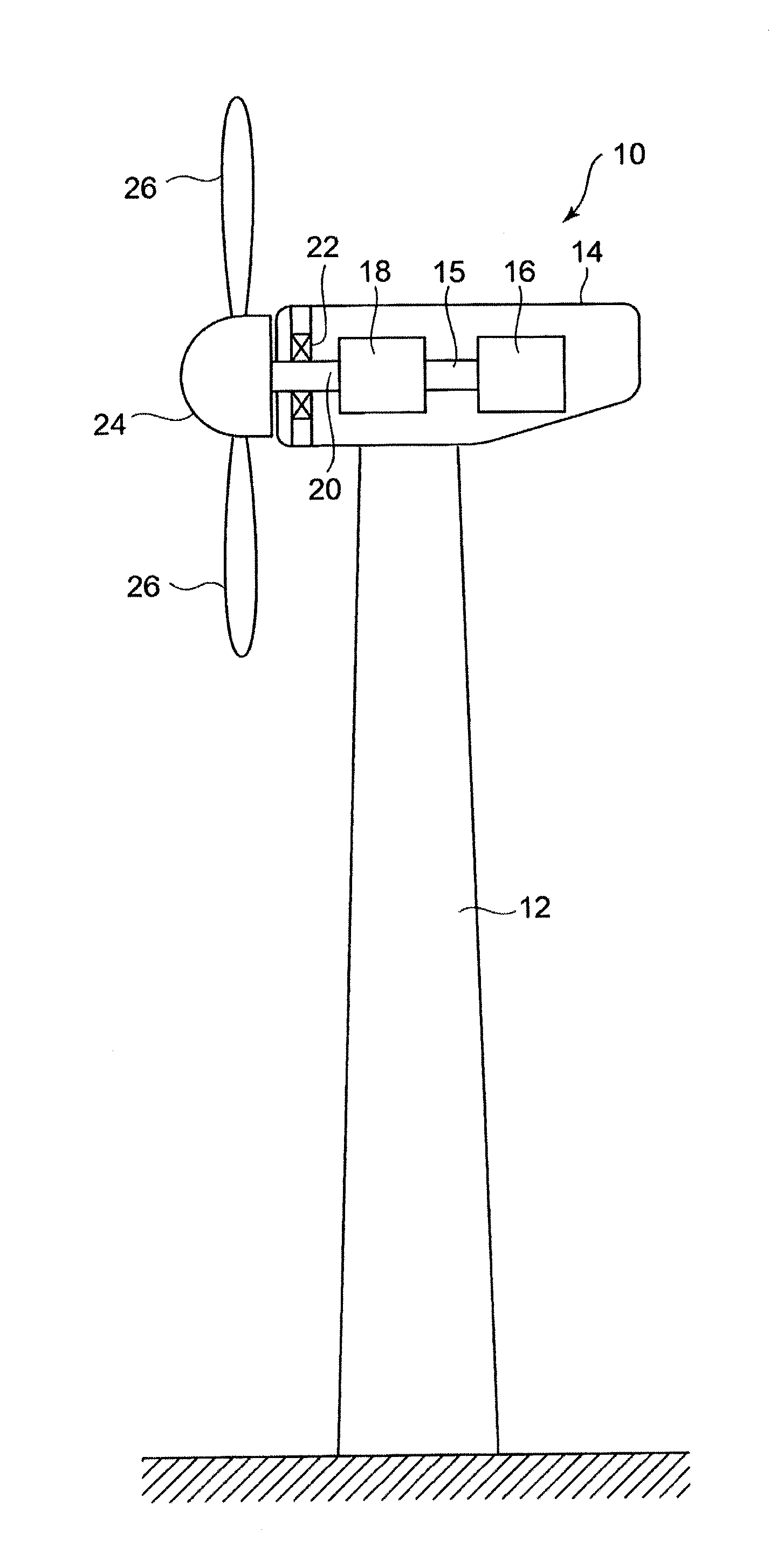
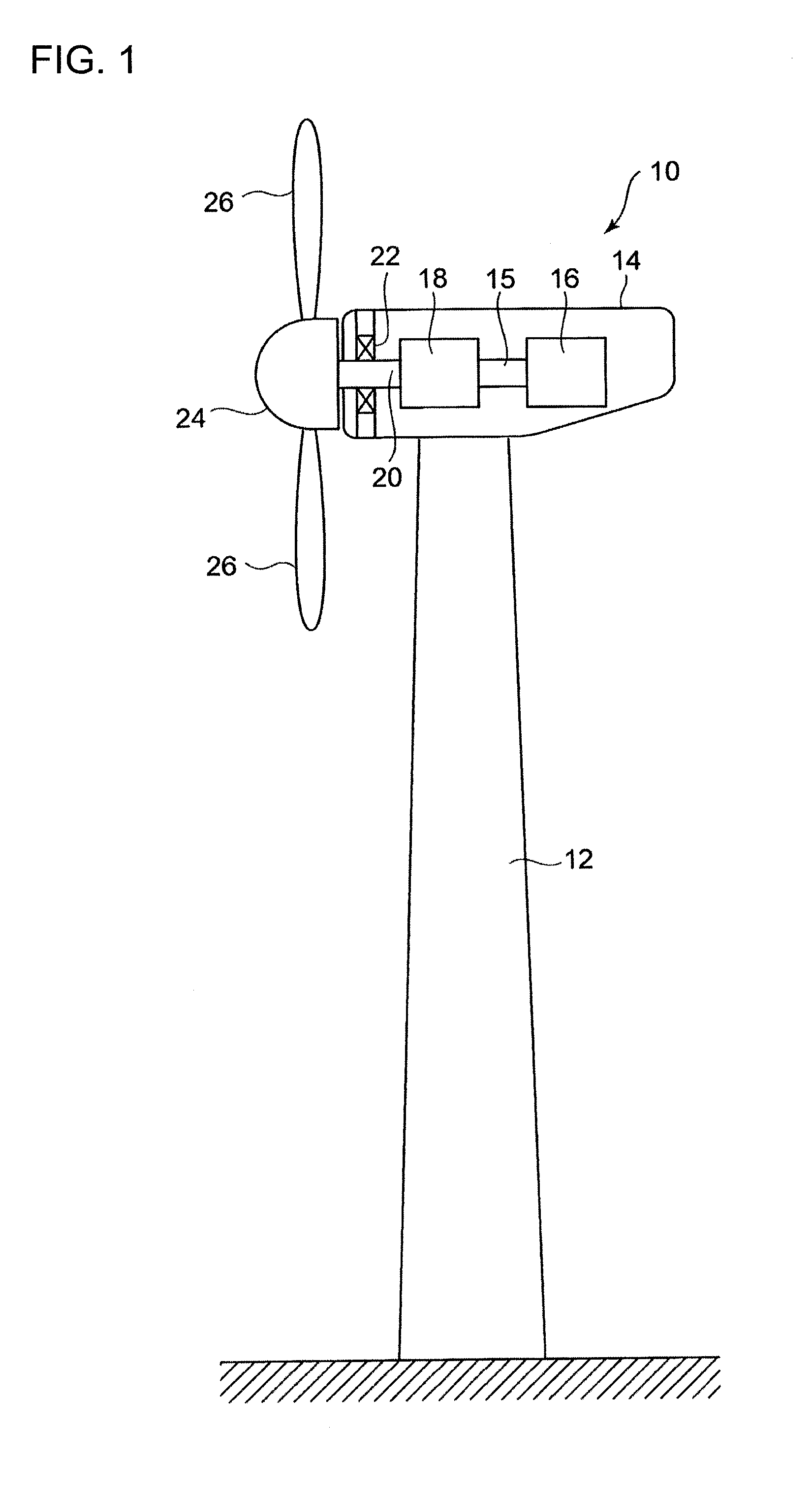
[0055]FIG. 1 is a schematic illustration of a wind turbine for wind power generation 10. The wind turbine for wind power generation 10 is provided with a tower 12 installed on the ground, for instance. A nacelle 14 is installed on the tower 12. A generator 16 and a step-up gear 18 are installed in the nacelle 14. The generator 16 and the step-up gear 18 are connected to each other via a shaft 15. A main shaft 20 is connected to the step-up gear 18 at one end. The step-up gear 18 is formed of, for instance, a planetary gear mechanism.

[0056]A main shaft bearing 22 is provided in the nacelle 14 to support the main shaft 20 rotatably. The main shaft 20 extends almost horizontally and a front-end side of the main shaft 20 protrudes from the nacelle 14.

[0057]At the end of the main shaft 20, a rotor head 24 is fixed. To the rotor head 24, blades (e.g. three blades in the drawing) are radially attached. More specifically, this wind turbine for wind power generation 10 is a propeller windmil...

second embodiment

[0081]The impact load monitoring system of a second embodiment is explained in reference to drawings. The same reference numerals are given without adding explanations for those configurations that are the same or substantially the same as the first embodiment.

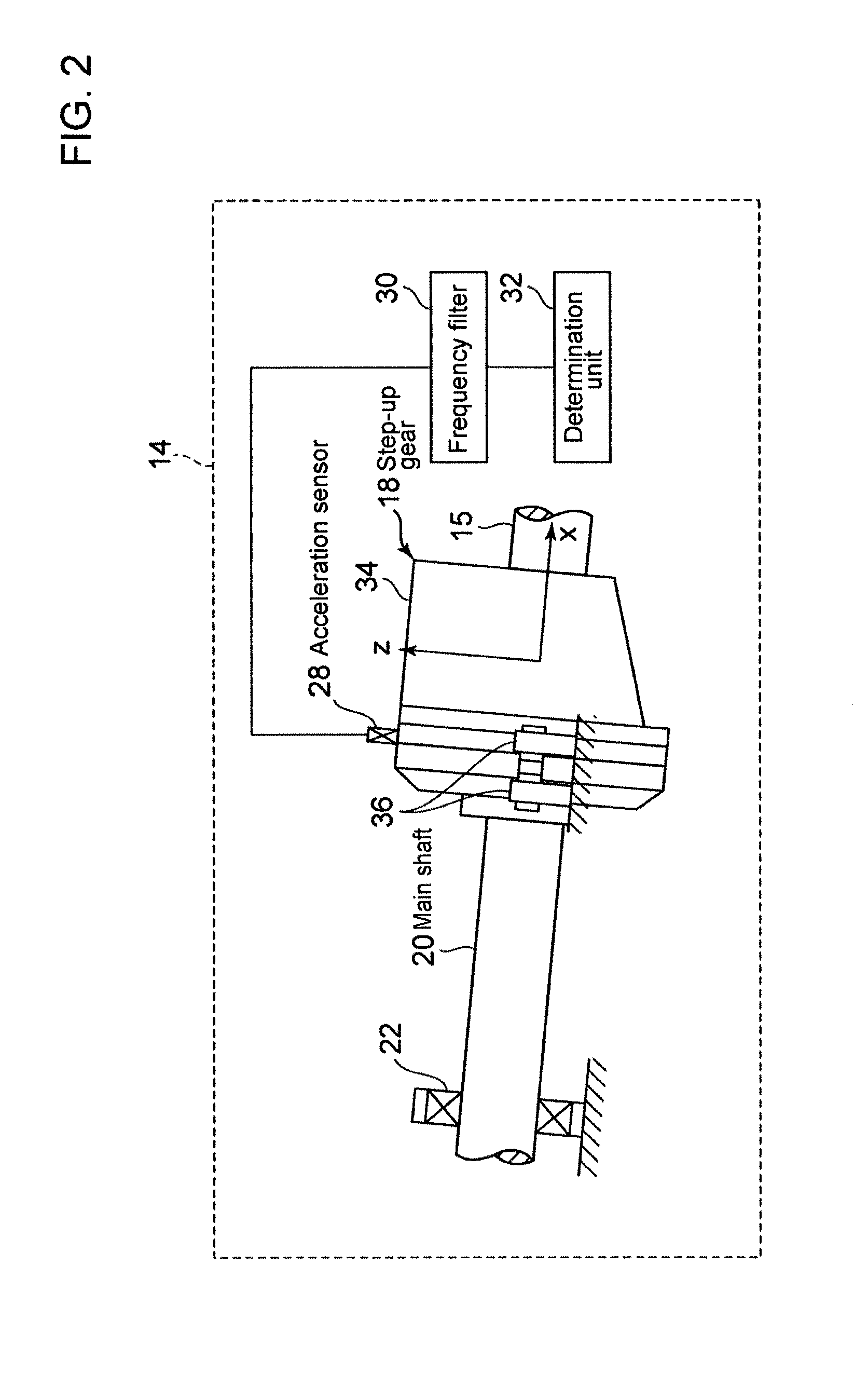
[0082]The impact load monitoring system of the second embodiment is different from that of the first embodiment in that acceleration sensor 28 is attached to the main shaft 22 as shown in FIG. 10.

[0083]According to the impact load monitoring system of the second embodiment, it is possible to determine whether or not the impact load is applied with respect to the main bearing 22 and thus appropriate actions can be taken in accordance with the determination result.

[0084]While the embodiments of the present invention have been described, it is obvious to those skilled in the art that various changes may be made without departing from the scope of the invention.

[0085]For instance, in the first and second embodiments, the accelerat...


PUM


Abstract

An impact load monitoring system for a wind turbine for wind power generation is provided with: an acceleration sensor 28 attached to a step-up gear 18 connected to a main shaft 20; a frequency filter 30 for extracting a monitoring-object component contained in a target frequency domain from vibration data representing a temporal change of amplitude of the acceleration obtained by the acceleration sensor 28; and a determination unit 32 for determining whether or not amplitude of acceleration of the monitoring-object component exceeds a reference value which is set in advance, by comparing the amplitude of the acceleration with the reference value.

Description

TECHNICAL FIELD[0001]The present invention relates to an impact load monitoring system and an impact load monitoring method for a wind turbine for wind power generation.BACKGROUND ART[0002]A wind turbine for wind power generation includes, for instance, a tower installed on the ground, a nacelle placed atop the tower, a rotor head rotatably attached to the nacelle, and a plurality of blades attached radially to the rotor head. The rotor head is connected to one end of a main shaft. The other end of the main shaft extends within the nacelle. The main shaft is rotatably supported by a main bearing provided in the nacelle. A step-up gear provided in the nacelle is connected to the other end of the main shaft and the step-up gear is connected to a generator. Upon rotation of the rotor head by wind against the blades, the rotational force is inputted to the generator via the main shaft and the step-up gear so as to generate power by the generator.[0003]In the main bearing and the step-up...

Claims


Application Information

Patent Timeline
Patent Type & Authority Applications(United States)
IPC IPC(8): G01M15/00
CPCG01M15/00Y02E10/722G01M7/00G01H1/003Y02E10/72
Inventor SHODA, KATSUHIKO
Owner MITSUBISHI HEAVY IND LTD
Why Eureka
Try Eureka