Rechargeable electric device

a technology of electric devices and battery packs, applied in the direction of electrochemical generators, secondary battery servicing/maintenance, transportation and packaging, etc., can solve the problem of causing a great error between the count value and the remaining capacity of the secondary battery, and it is difficult for the display unit corresponding to the count value to accurately display the full charge state.

Inactive Publication Date: 2013-07-04
PANASONIC INTELLECTUAL PROPERTY MANAGEMENT CO LTD
View PDF2 Cites 534 Cited by
  • Summary
  • Abstract
  • Description
  • Claims
  • Application Information

AI Technical Summary

Benefits of technology

[0008]With the rechargeable electric device according to the first aspect of the present invention, the full charge display is implemented when the count value reaches the value corresponding to the full charge of the

Problems solved by technology

Depending on the factor described above or the load condition, as the case may be, there was a fear of causing an error between the count value and the remaining capacity of the secondary battery.
That is, the count value becomes mach smaller than the actual remaining capacity of the secondary battery, leaving remaining capacity of the second battery estimated by the count value to be considerably smaller than the actual remaining cap

Method used


Image

  • Rechargeable electric device
  • Rechargeable electric device
  • Rechargeable electric device

Examples


first embodiment

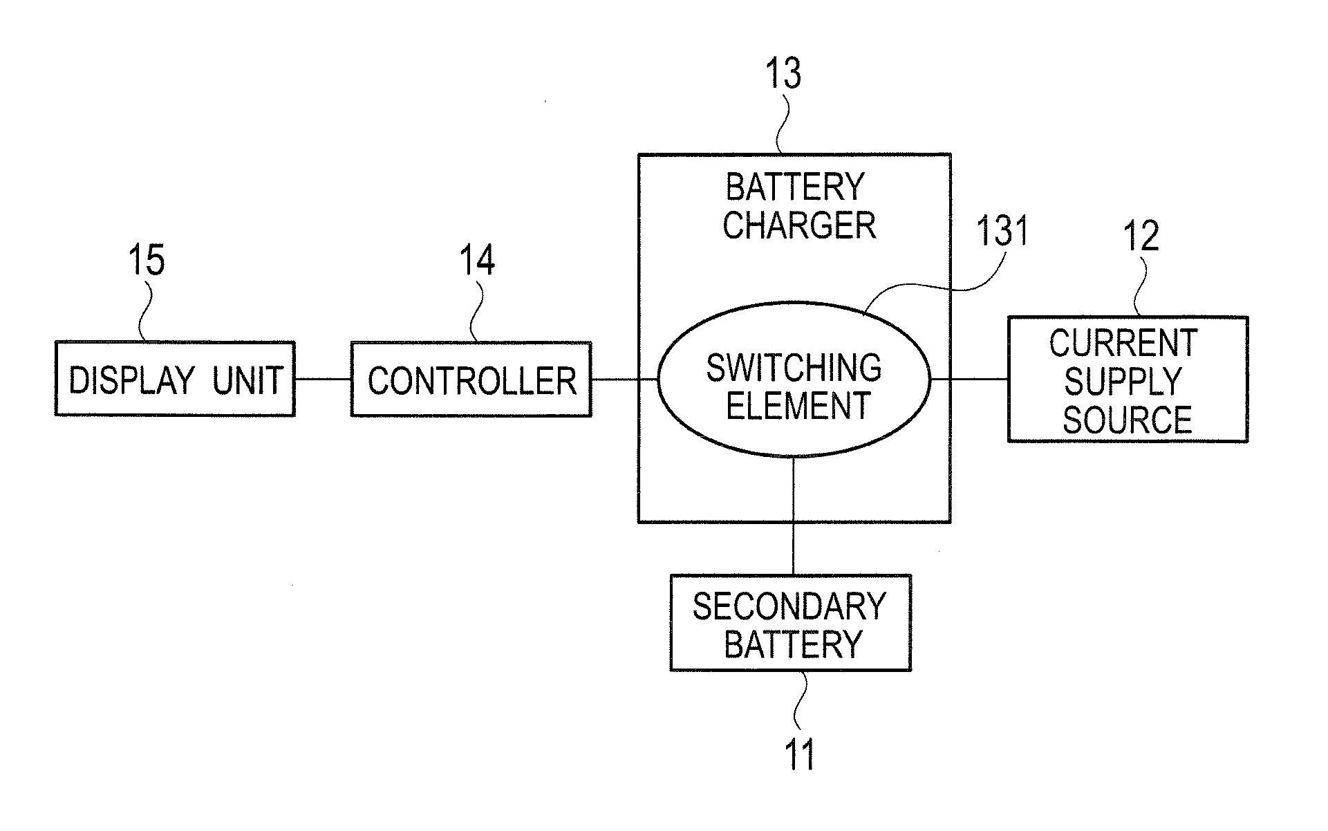
[0017]A rechargeable electric device according to a first embodiment illustrated in FIG. 1 includes a secondary battery 11, a current supply source 12, a battery charger 13, a controller 14, and a display unit 15.

[0018]The secondary battery 11 includes, for example, a nickel-metal hydrogen battery, a nickel-cadmium battery, or the like, and is charged with a charging current supplied from the current supply source 12 by way of the battery charger 13.

[0019]The current supply source 12 supplies a direct current to the battery charger 13. The direct current is supplied from, for example, a commercial AC power source of about 100 V to 240 V by way of an AC adapter.

[0020]The battery charger 13 includes a switching element 131 such as transistor. The switching element 131 is connected between the secondary battery 11 and the current supply source 12. The switching element 131 receives the direct current supplied from the current supply source 12, controls and adjusts the charge current su...

second embodiment

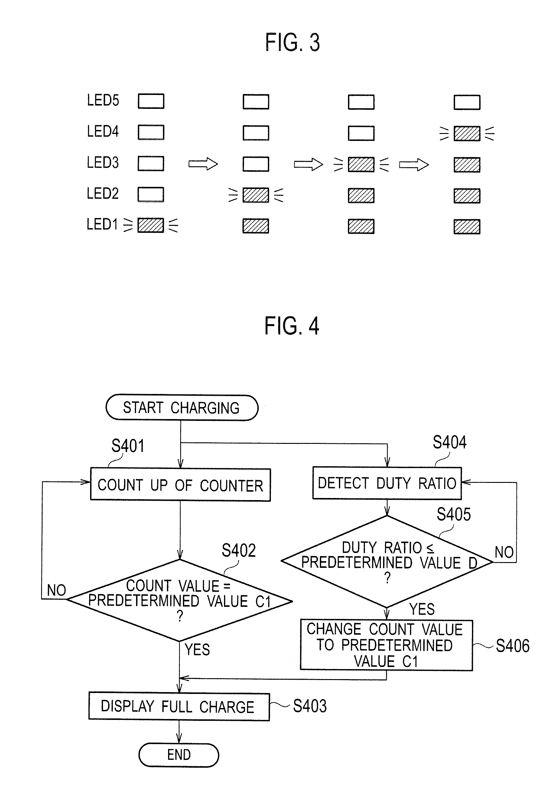
[0034]In accordance with a rechargeable electric device according to a second embodiment, FIG. 5 is a flowchart illustrating procedures of the displaying operation processes by the display unit 15 at the time of charging the secondary battery 11. The procedures illustrated in the flowchart of FIG. 5 have such a characteristic as that, compared with the procedures illustrated in FIG. 4, the processes at steps S501 and S502 are added before the processes at steps S401 and S404 in FIG. 4 after starting the charging, with other characteristics being like those in FIG. 4. Thus, in FIG. 5, the steps S503 to S505 are like the steps S401 to S403 in FIG. 4 while steps S506 to S508 are like steps S404 to S406 in FIG. 4.

[0035]In FIG. 5, first, the charging of the secondary battery 11 is started, and the counter makes count up per preset constant time, to thereby add the count value (step S501). Then, it is determined whether or not the count value has reached a predetermined value C2, herein “...


PUM


Abstract

Under a control by a controller (14), a rechargeable electric device makes a full charge display to display on a display unit (15) that a secondary battery (11) is fully charged, after a start of charging the secondary battery (11) in a case where either when a count value of a counter reaches a first predetermined value (C1) corresponding to the full charge of the secondary battery (11), or when a duty ratio of switching signals which make an on/off control of a switching element (131) becomes smaller than or equal to a predetermined value (D) corresponding to the charge current obtained at a time of the full charge of the secondary battery (11).

Description

TECHNICAL FIELD[0001]The present invention relates to a rechargeable electric device for charging a secondary battery, and especially, relates to a rechargeable electric device displaying a remaining capacity of the secondary battery at the time of charging the secondary battery.BACKGROUND ART[0002]As this type of conventional technology, one described in PTL 1 is known. PTL 1 describes a technology for virtually estimating an present battery capacity by counting up a count value per constant time at the mode of charging the secondary battery, to thereby allow the displaying operation at a battery capacity display unit to have an interlocking property corresponding to the count value.CITATION LISTPatent Literature[0003]PTL 1: JP 7-264782 ASUMMARY OF INVENTION[0004]According to the technology of PTL 1, there was such a fear as, when the charging operation was not interlocked with the full charge display, the waiting electric power might be increased due to continuation of the chargin...

Claims


Application Information

Patent Timeline
IPC IPC(8): H02J7/00
CPCH01M10/44H01M10/488H02J2007/0049H02J7/0077H02J7/0047H02J7/0049H02J7/00712Y02E60/10H02J7/0048
Inventor WATANABE, KAZUNORIASAKAWA, KOJIIWAO, SEIICHI
Owner PANASONIC INTELLECTUAL PROPERTY MANAGEMENT CO LTD
Why Eureka
Try Eureka