Charge Roller for an Image Forming Apparatus Using Hard Filler Particles

Active Publication Date: 2013-07-04
LEXMARK INT INC
View PDF5 Cites 38 Cited by
  • Summary
  • Abstract
  • Description
  • Claims
  • Application Information

AI Technical Summary

Benefits of technology

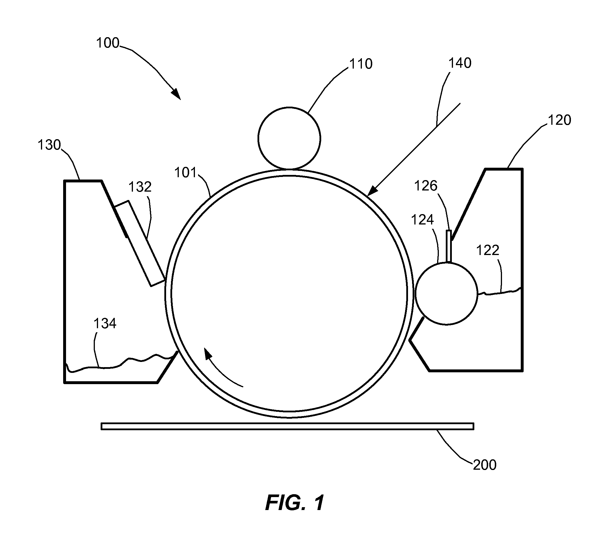
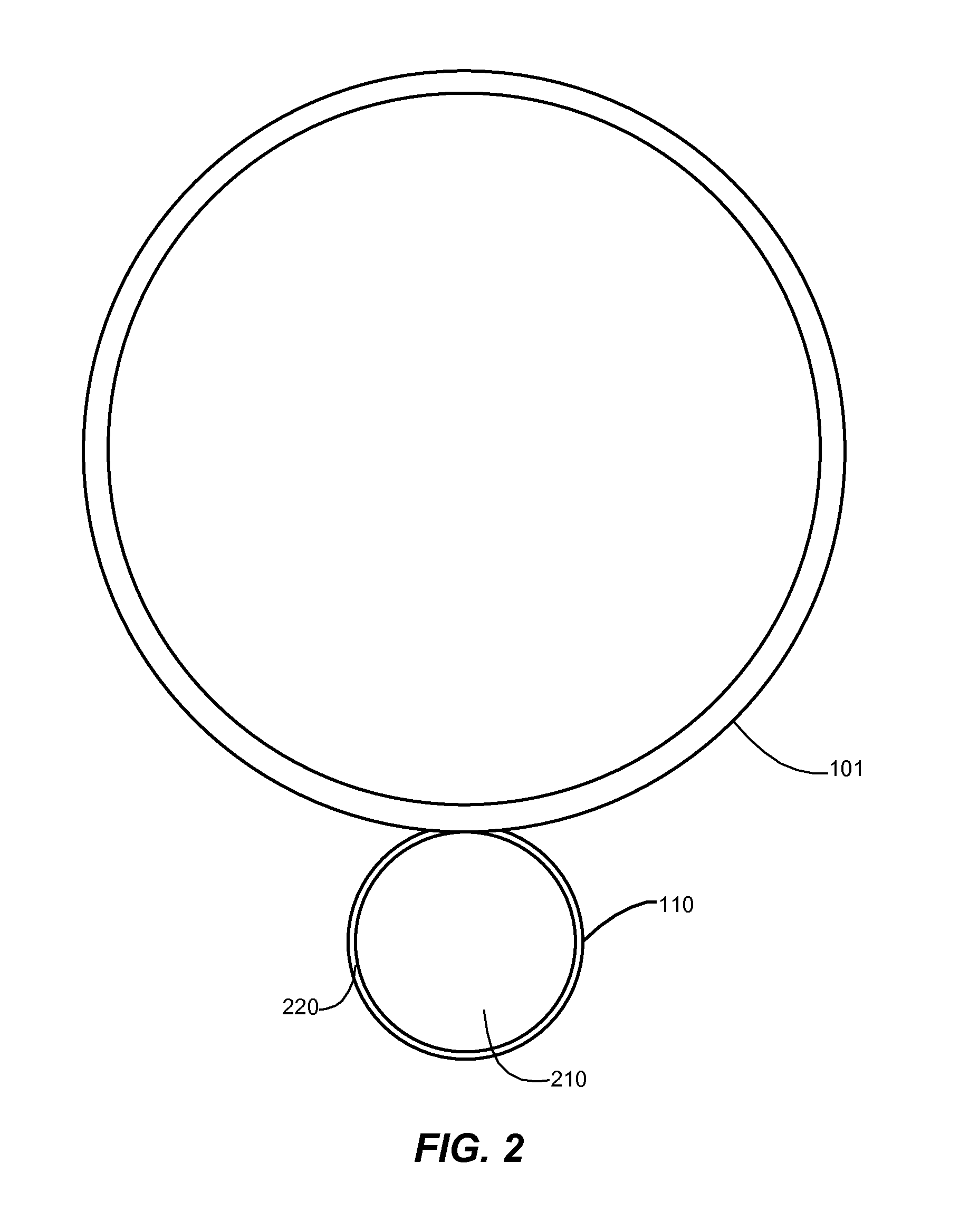
[0014]Embodiments of the present disclosure overcome shortcomings of prior charge rolls and thereby satisfy a significant need for a charge roll having improved resistance to defects from prolonged periods of nonuse. According to example embodiments, the charge roller includes a cylindrical core having an outer surface, and an outermost coating layer covering the outer surface of the cylindrical core. The outermost coating layer includes a coating material and filler particles. The filler particles have an average particle size larger than an average thickness of the outermost coating layer in a portion or area without the f

Problems solved by technology

It is commonly known that a charge roller may generate defects in a printed image after prolonged static contact with a photoconductor drum, especially if the contact occurs at higher temperature and humidity such as during shipping and warehouse storage.
These charge roller defects may be chemical or mechanical in nature and can result in print defects in a printed image of the electrophotographic device.
Chemical defects may be due to the migration or leaching of low molecular weight components of the charge roll core material which may attack the outer surface of the charge roller or the coating layer of the photoconductor drum.
Mechanical defects may be related to the formation of a dent or flat spot on the outer surface of the charge roller which may be due to the high contact pressure exerted between the charge roller and th

Method used


Image

  • Charge Roller for an Image Forming Apparatus Using Hard Filler Particles
  • Charge Roller for an Image Forming Apparatus Using Hard Filler Particles
  • Charge Roller for an Image Forming Apparatus Using Hard Filler Particles

Examples


Embodiment Construction

[0020]It is to be understood that the invention is not limited in its application to the details of construction and the arrangement of components set forth in the following description or illustrated in the drawings. The invention is capable of other embodiments and of being practiced or of being carried out in various ways. Also, it is to be understood that the phraseology and terminology used herein is for the purpose of description and should not be regarded as limiting. The use of “including,”“comprising,” or “having” and variations thereof herein is meant to encompass the items listed thereafter and equivalents thereof as well as additional items. Further, the terms “a” and “an” herein do not denote a limitation of quantity, but rather denote the presence of at least one of the referenced item.

[0021]Reference will now be made in detail to the example embodiment(s), as illustrated in the accompanying drawings. Whenever possible, the same reference numerals will be used througho...


PUM


Abstract

An image forming apparatus includes a charge roller with improved resistance to defects from prolonged periods of nonuse. The charge roller includes an outermost coating layer including a coating material and filler particles. The filler particles have an average particle size larger than an average thickness of the outermost coating layer in a portion without the filler particles. Furthermore, the filler particles are harder and have a higher glass transition temperature than the coating material.

Description

CROSS REFERENCES TO RELATED APPLICATIONS[0001]Pursuant to 35 U.S.C. §119, this application claims the benefit of the earlier filing date of Provisional Application Ser. No. 61 / 581,862, filed Dec. 30, 2011, entitled “A Charge Roller for an Image Forming Apparatus Using Hard Filler Particles,” the content of which is hereby incorporated by reference herein in its entirety.STATEMENT REGARDING FEDERALLY SPONSORED RESEARCH OR DEVELOPMENT[0002]None.REFERENCE TO SEQUENTIAL LISTING, ETC.[0003]None.BACKGROUND[0004]1. Field of the Disclosure[0005]The present disclosure generally relates to imaging and, more particularly, to an imaging device having a charge roller with improved resistance to defects from prolonged periods of inactivity.[0006]2. Description of the Related Art[0007]Generally, there are two distinct types of charge rollers used in electrophotographic devices such as laser printers. The first type is a charge roller which includes a core material whose surface may be modified by ...

Claims


Application Information

Patent Timeline
IPC IPC(8): G03G15/02
CPCG03G15/0233
Inventor MARTINKOVIC, MATTHEW THOMASGOEBEL, BENJAMIN JOHN
Owner LEXMARK INT INC
Why Eureka
Try Eureka