Prosthetic foot with resilient heel

Active Publication Date: 2013-07-04
OSSUR HF
View PDF14 Cites 26 Cited by
  • Summary
  • Abstract
  • Description
  • Claims
  • Application Information

AI Technical Summary

Benefits of technology

[0017]In certain embodiments, the heel member can have at least one rib on the bottom surface to create a horizontal displacement of the foot at heel strike, increasing stability and providing a more natural gait for the user. In certain embodiments, the heel member can

Problems solved by technology

Some prosthetic foot designs employ support members located in the heel region of the prosthetic foot; however, such support members fail to provide adequate cush

Method used


Image

  • Prosthetic foot with resilient heel
  • Prosthetic foot with resilient heel
  • Prosthetic foot with resilient heel

Examples


Example

[0028]An objective of one or more embodiments described below is to provide a prosthetic foot with a lightweight and / or cushioning heel member. In select embodiments, the heel member advantageously provides improved stability and balance, while providing a more natural gait for low activity users. Other embodiments provide only some of these benefits.

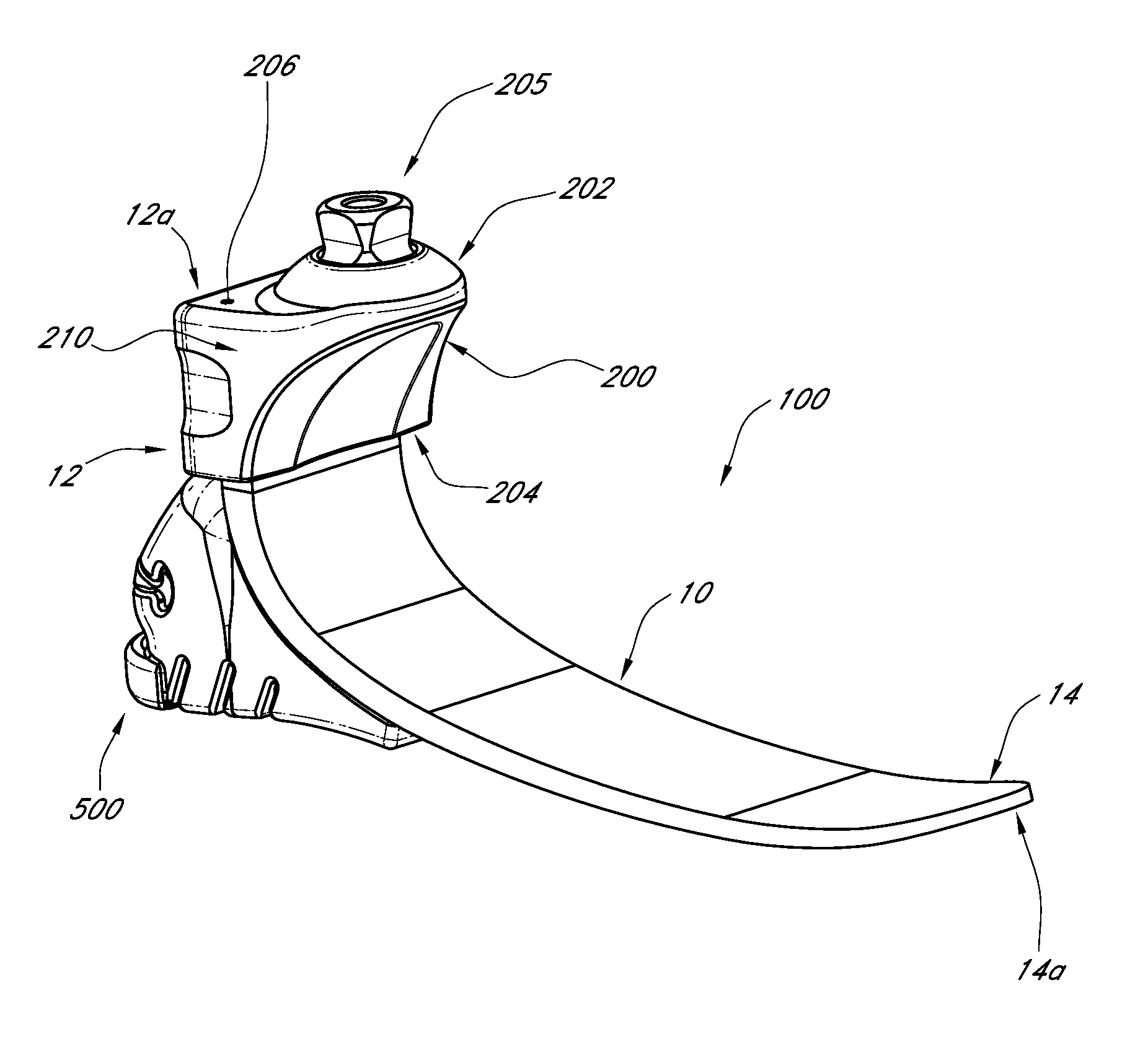
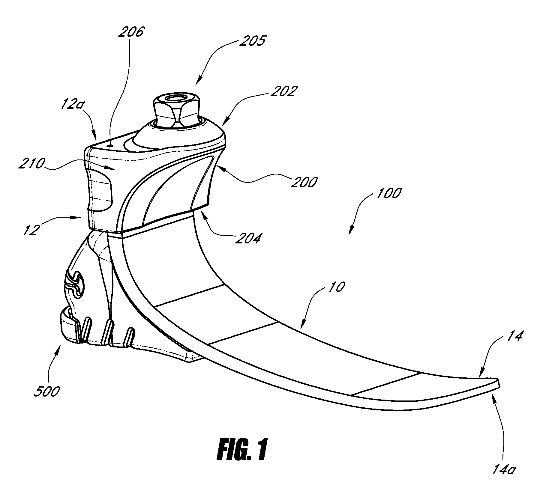
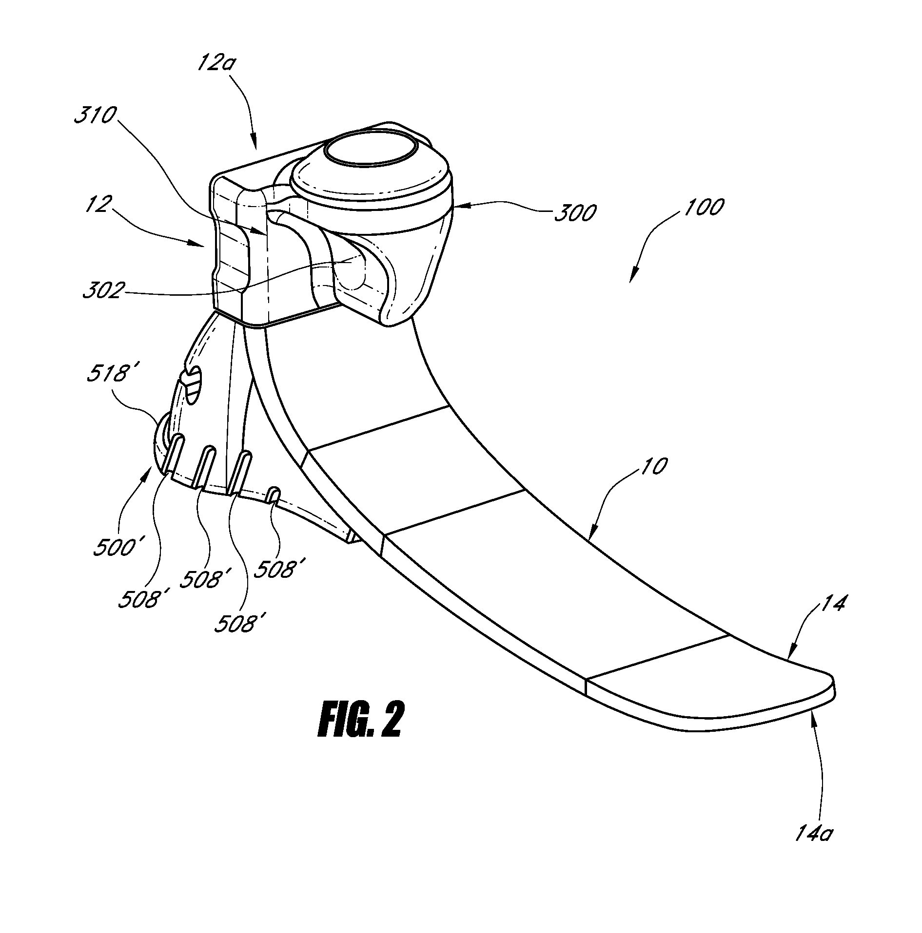
[0029]FIG. 1 illustrates one embodiment of a prosthetic foot 100 with a resilient heel member 500, which is described further below. The prosthetic foot 100 can have a foot member 10 that extends from a proximal section 12 to a distal section 14. In the illustrated embodiment, the proximal section 12 can be generally vertically oriented (see e.g., FIGS. 1 and 9), and the distal section 12 can be generally horizontally oriented. The foot member 10 can have a curved portion 16 between the proximal section 12 and the distal section 14. The proximal section 12 can extend to a proximal end 12a and can be generally near the location of a natu...


PUM


Abstract

A prosthetic foot can include a resilient heel member that can be removably coupled to the bottom of a plate-like foot member of the prosthetic foot. The heel member can be made of a resilient material, such as foam. The heel member can have a shape that corresponds to a foot cover and allows the prosthetic foot to fit within a foot cover. A lip may be provided to engage with a corresponding portion of the foot cover to secure the heel member within the foot cover. A rib can be located on the bottom of the heel member to create horizontal or vertical displacement of the foot at heel strike. A recess can be created in the heel member to removably receive an insert, which can alter the stiffness of the heel member.

Description

CROSS-REFERENCE TO RELATED APPLICATIONS[0001]This application claims the benefit of U.S. Provisional Patent Application No. 61 / 581,580, entitled “Prosthetic Foot with Resilient Heel for Low Activity Users,” and filed Dec. 29, 2011, the entire contents of which are incorporated herein by reference and should be considered part of this specification.BACKGROUND[0002]1. Field[0003]The present application relates, in certain embodiments, to prosthetic devices. In particular, certain embodiments of the present application relate to a prosthetic foot with a resilient heel.[0004]2. Description of the Related Art[0005]Prosthetic feet of different designs are well known in the art. The various conventional designs have sought to solve various limitations associated with prosthetic feet.[0006]Some prosthetic foot designs employ support members located in the heel region of the prosthetic foot; however, such support members fail to provide adequate cushioning, stability, and balance for the use...

Claims


Application Information

Patent Timeline
IPC IPC(8): A61F2/42
CPCA61F2/4225A61F2/66A61F2002/6678A61F2002/5007A61F2002/6614A61F2002/6642
Inventor LECOMTE, CHRISTOPHEBJORNSDOTTIR, MARTAGUNNSTEINSSON, LARUS
Owner OSSUR HF
Why Eureka
Try Eureka