Circuit assembly yield prediction with respect to manufacturing process

a technology of manufacturing process and yield prediction, applied in the field of tools for predicting the yield of circuit assembly, can solve the problems of many prediction techniques failing to account for many, difficult yield prediction, and possible failure scenarios of circuit assembly

Active Publication Date: 2013-07-04
FLEXTRONICS AP LLC
View PDF23 Cites 20 Cited by
  • Summary
  • Abstract
  • Description
  • Claims
  • Application Information

AI Technical Summary

Benefits of technology

[0006]Among other things, systems and methods are described for automatically predicting production yield for a circuit assembly according to attributes of its components and defect data mapped thereto. In one embodiment, a proposed design specification for a circuit assembly, including bill of materials (BOM) and schematic data, is received at a yield prediction environment for analysis. The yield prediction environment maps a set of attributes to each component in the BOM and maps a set of possible defects to each component (or component type) according to its attributes. Defects may be further mapped to a manufacturing process assigned to populate each component in the circuit assembly. The defects are associated with predicted frequencies of occurrence, which can be used to roll up a predicted yield (e.g., or remediation cost, etc.) for the circuit assembly. The yield prediction environment further allows “what-if” analyses to be performed so that different yield prediction results can be compared as a function of different form factor options and / or different manufacturing process options.

Problems solved by technology

However, yield prediction can be difficult for a number of reasons.
Further, as component counts increase, the possible failure scenarios for the circuit assembly can increase dramatically.
Indeed, traditional yield prediction techniques fail to account for many of these factors and have tended to provide unreliable results.
For example, many traditional techniques provide crude representations and / or groupings of the components being used in the circuit assembly (e.g., ignoring lead type, pitch, rotation, etc.) and do not account for the type of manufacturing process being used or screening techniques that may be available at different points in the manufacturing process.
Further, traditional techniques typically do not account for feedback (e.g., from testing methodologies, actual factory yields, etc.) to tune yield predictions.

Method used


Image

  • Circuit assembly yield prediction with respect to manufacturing process
  • Circuit assembly yield prediction with respect to manufacturing process
  • Circuit assembly yield prediction with respect to manufacturing process

Examples


Embodiment Construction

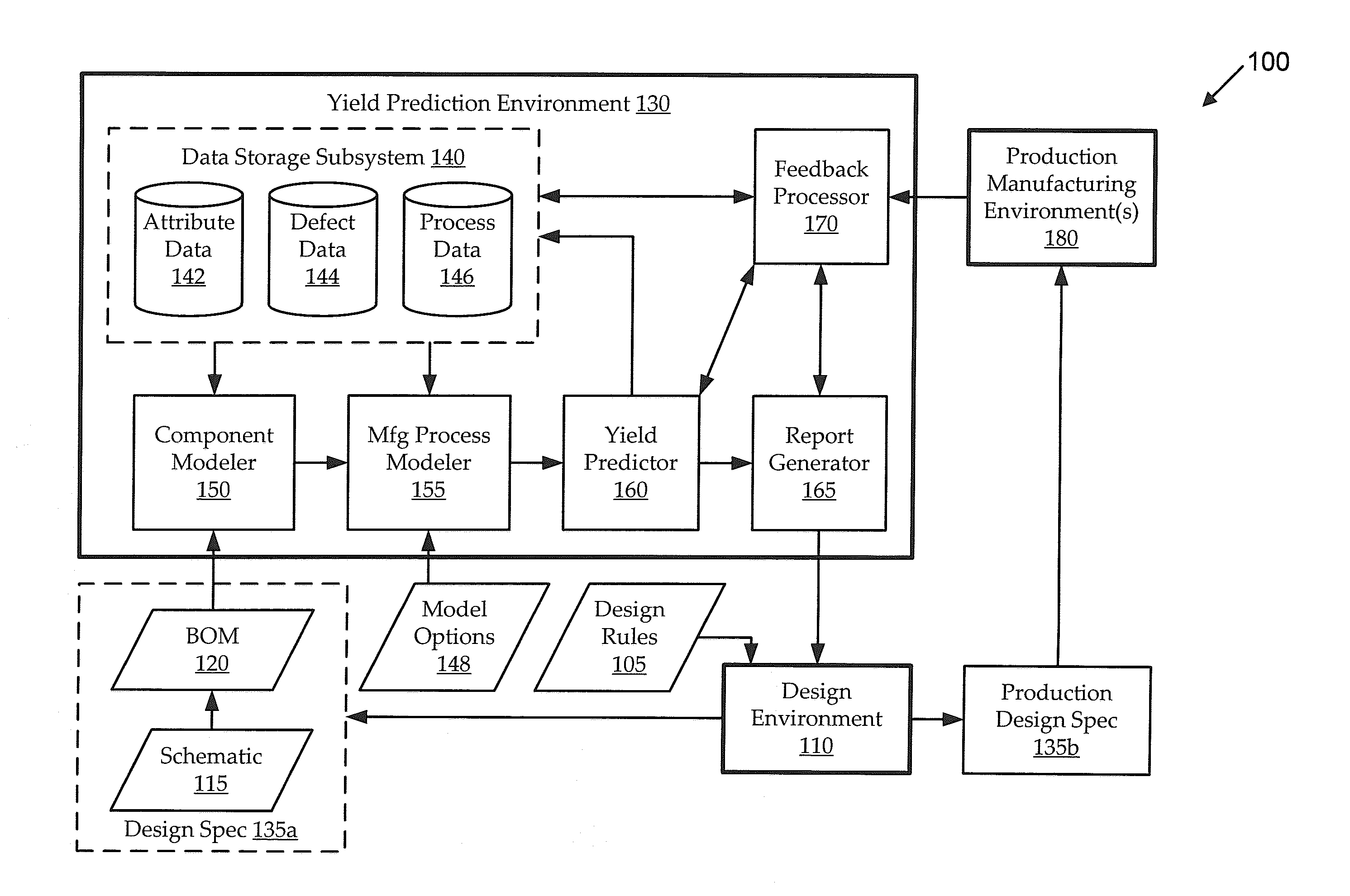
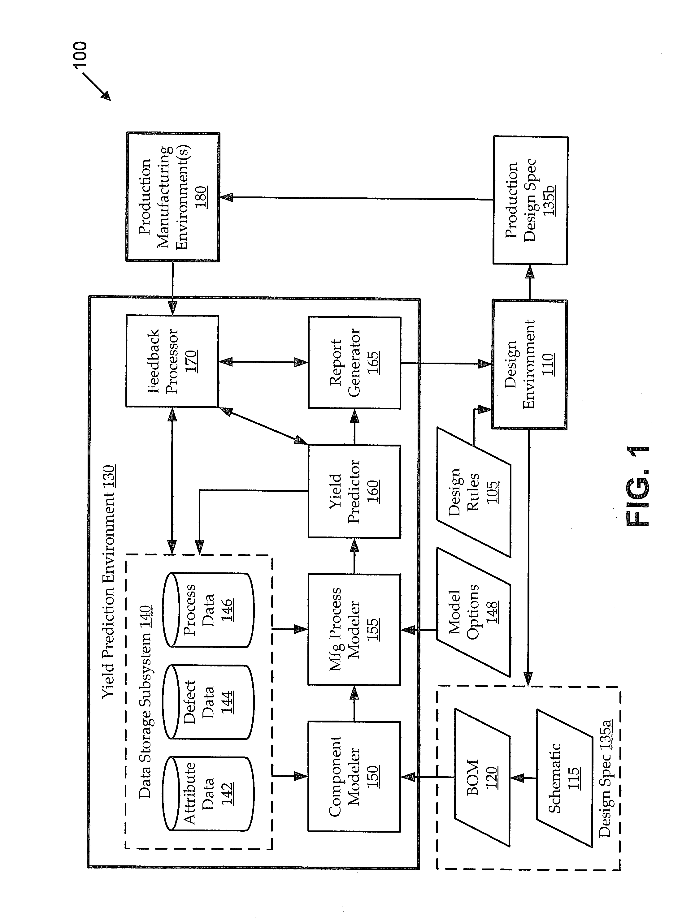
[0017]It is often desirable to design electronic circuit assemblies with an eye toward the manufacturing environment in which the circuit assembly will be produced. Even a circuit assembly that is designed to have highly reliable electrical functionality may be manufactured in various ways with widely varying practical yields. However, accurately predicting those yields is typically impractical or impossible using traditional yield prediction techniques, which tend to ignore many of the large number of potentially relevant variables. For example, the manufacturing yield for a particular circuit may be appreciably impacted by selections of component parts to perform certain functionality (e.g., component reliability, lead type, packaging constraints, power constraints, etc.), placement and / or arrangement of those components in the circuit assembly (e.g., including rotation and / or pitch of the components), form factor (e.g., size and shape) constraints of the circuit assembly, carrier...


PUM


Abstract

Embodiments of the invention include systems and methods for automatically predicting production yield for a circuit assembly according to attributes of its components and defect data mapped thereto. Embodiments receive a proposed design specification for a circuit assembly, including bill of materials (BOM) and schematic data, at a yield prediction environment. The yield prediction environment maps a set of attributes to each component in the BOM and maps a set of possible defects to each component according to its attributes. Defects may be further mapped to a manufacturing process assigned to populate each component in the circuit assembly. The defects are associated with predicted frequencies of occurrence, which can be used to roll up a yield prediction for the circuit assembly. Embodiments further allow “what-if” analyses to be performed so that different yield prediction results can be compared according to different form factor options and / or different manufacturing process options.

Description

CROSS-REFERENCES[0001]This application is a continuation of U.S. patent application Ser. No. 13 / 410,179, filed on Mar. 1, 2012, entitled “CIRCUIT ASSEMBLY YIELD PREDICTION WITH RESPECT TO MANUFACTURING PROCESS,” and claims priority from U.S. Provisional Patent Application No. 61 / 581,488, filed on Dec. 29, 2011, entitled “YIELD PREDICTION TOOL,” which is hereby incorporated by reference, as if set forth in full in this document, for all purposes.BACKGROUND[0002]Embodiments relate generally to the field of circuit assembly manufacturing, and more particularly to tools for predicting circuit assembly yields with respect to component placement manufacturing processes.[0003]Electronic devices and systems typically include at least one circuit assembly. The circuit assembly includes a number of circuit components (e.g., discrete components, integrated circuits, circuit sub-assemblies, etc.) that may be coupled to a carrier having conductive and / or non-conductive features (e.g., a printed ...

Claims


Application Information

Patent Timeline
Patent Type & Authority Applications(United States)
IPC IPC(8): G06F17/50G16Z99/00
CPCG06F17/5081G06F2217/14G06F17/5009G06F17/18G06F17/15G06F17/11G06F19/00G01R31/26G01R31/02G01R31/003G01R27/00G06F11/008G06F2217/12G01R31/08G06F2217/10G16Z99/00G06F2111/08G06F30/398G06F30/20G06F30/333G06F2119/18
Inventor DURKAN, MICHAEL ANTHONY
Owner FLEXTRONICS AP LLC
Why Eureka
Try Eureka