Generator assembly apparatus

Active Publication Date: 2013-07-11
SIEMENS GAMESA RENEWABLE ENERGY AS
View PDF16 Cites 5 Cited by
  • Summary
  • Abstract
  • Description
  • Claims
  • Application Information

AI Technical Summary

Benefits of technology

[0026]Such a manual correction can be time-consuming and may be error-prone. Therefore, in one embodiment, the generator assembly apparatus comprises a controlling means for controlling a linear actuator on the basis of a measurement signal delivered by a sensor. The controlling means can be, for example, a hand-held module that receives measurement signal, analyses them, and provides an indication of which adjustment means or moving means must be manipulated, and by how much, to achieve the desired separation. In one

Problems solved by technology

The physical dimensions and weight of such a large generator pose problems during its assembly.
Handling of the heavy, unwieldy and vulnerable components is complex and time-consuming, and is also hazardous, so that strict safety measures must be adhered to.
This adds considerably to the overall time and cost required for the assembly of a direct-drive generator.
In particular, the merging of a large rotor with a correspondingly large stator equipped with many windings can be problematic, since a very small separation—us

Method used


Image

  • Generator assembly apparatus
  • Generator assembly apparatus
  • Generator assembly apparatus

Examples


Embodiment Construction

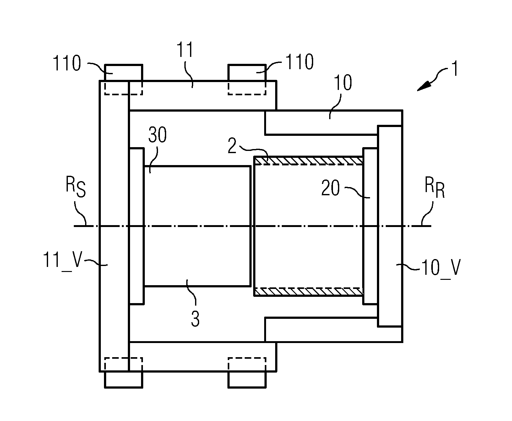
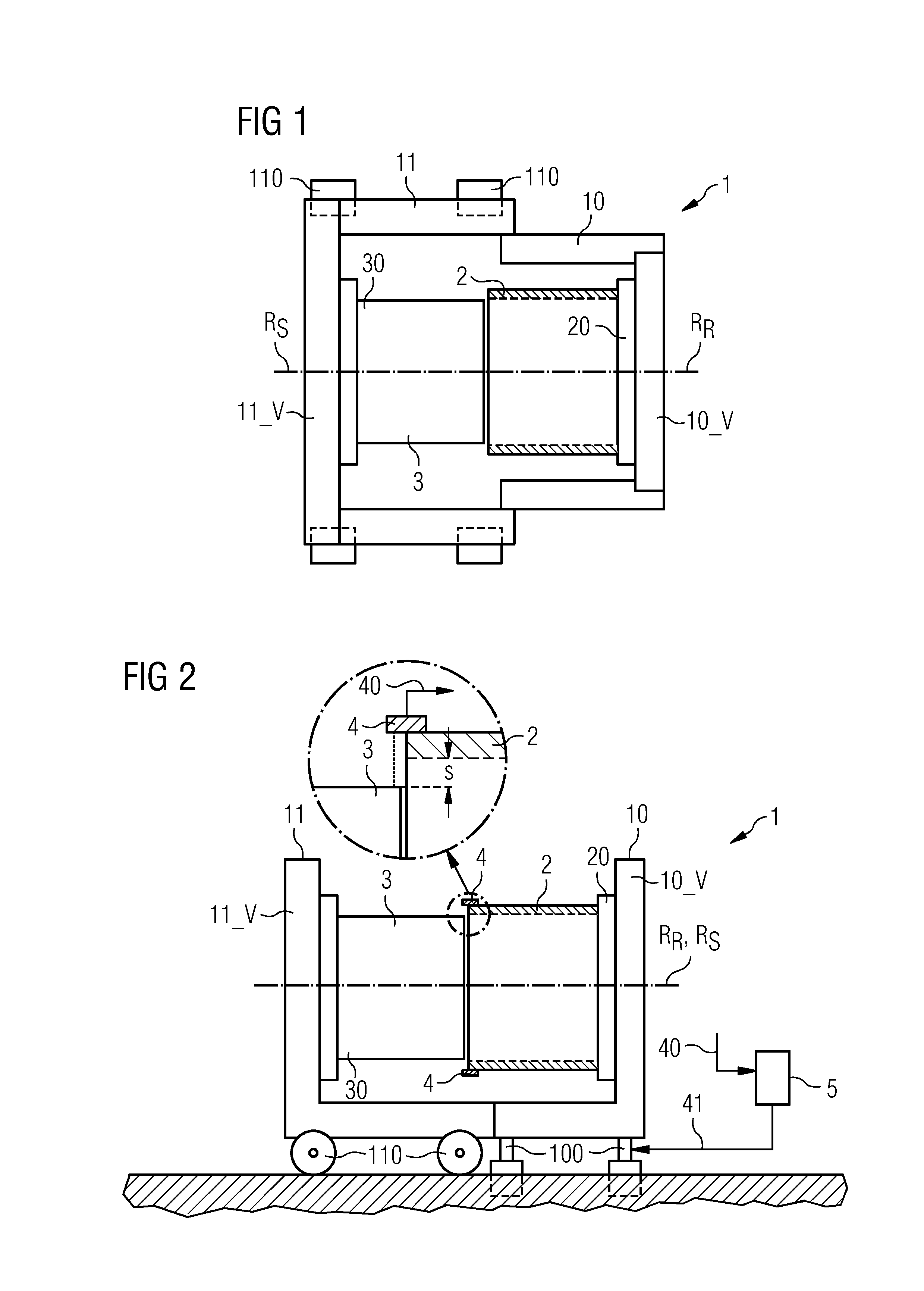
[0034]FIG. 1 shows a generator assembly apparatus 1 according to one embodiment, in a first merging stage, shown from above. Here, a stator support frame 11 bearing a horizontally oriented stator 3 has been moved in place in front of a rotor support frame 10 bearing a horizontally oriented rotor 2. In this embodiment, one outer end portion 30 of the stator 3 is fastened at its hub-side to a vertical frame portion 11_V or mounting surface 11_V of the stator support frame 11, while the rotor 2 is fastened at its nacelle-side to a vertical frame portion 10_V or mounting surface 10_V of the rotor support frame 10. In this embodiment, a bearing 20 has already been mounted to the rotor 2 as an outer end portion 20, and this bearing 20 is securely mounted to the vertical frame portion 10_V of the rotor support frame 10. The rotor 2, in this case an outside rotor 2, may or may not already have been equipped with a plurality of magnets. The diagram shows that the stator support frame 11 is d...


PUM


Abstract

A generator assembly apparatus is provided for merging a first annular component and a second annular component of a generator. The generator assembly apparatus includes first and second component support frames, a moving device and an adjustment device. The first component support frame supports the first component securely mounted to the first component support frame. The second component support frame supports the second component securely mounted to the second component support frame. The moving device moves one component support frame relative to the other component support frame to merge the components by inserting one component at least partially into an interior region of the other component. The adjustment device adjusts a position of a support frame such that a pre-defined separation between the first component and the second component is maintained during merging.

Description

CROSS REFERENCE TO RELATED APPLICATIONS[0001]This application claims priority of European Patent Office application No. 12150613.3 EP filed Jan. 10, 2012 and European Patent Office application No. 12192044.1 EP filed Nov. 9, 2012. All of the applications are incorporated by reference herein in their entirety.FIELD OF INVENTION[0002]The illustrated embodiments relate to a generator assembly apparatus and a method of merging a first annular component and a second annular component of a generator.BACKGROUND OF INVENTION[0003]Wind turbines are becoming more prevalent as these are increasingly used as a source of electricity. A direct-drive wind turbine has several advantages over a conventional wind turbine that comprises a gearbox, since a direct-drive wind turbine requires fewer parts, is less complex and more reliable. For these reasons, demand for direct drive wind turbines is increasing.[0004]A direct-drive generator has a relatively large diameter and many magnets of alternating p...

Claims


Application Information

Patent Timeline
IPC IPC(8): B23P11/00
CPCB23P11/00H02K7/1838H02K15/16Y10T29/53Y10T29/49826Y10T29/49009Y10T29/49012Y10T29/53143Y02E10/72H02K15/02H02K15/03H02K15/14
Inventor JENSEN, SOEREN JUULPEDERSEN, JOHN KRATHTHERKELSEN, RUNE ROENNE
Owner SIEMENS GAMESA RENEWABLE ENERGY AS
Why Eureka
Try Eureka