Die coolant system with an integral and automatic leak test

a technology of die cooling system and leak detection, which is applied in the direction of fluid tightness measurement, instruments, and foundation moulding equipment, etc., can solve the problems of quality issues of cast articles, leakage of die cooling water, and difficulty in detection and positioning of die leakage, etc., to achieve the effect of minimizing any workflow interruption

a technology of die cooling system and leak detection, which is applied in the direction of fluid tightness measurement, instruments, and foundation moulding equipment, etc., can solve the problems of quality issues of cast articles, leakage of die cooling water, and difficulty in detection and positioning of die leakage, etc., to achieve the effect of minimizing any workflow interruption

US20130174648A1Inactive Publication Date: 2013-07-11GM GLOBAL TECH OPERATIONS LLC

Image

  • Die coolant system with an integral and automatic leak test
  • Die coolant system with an integral and automatic leak test
  • Die coolant system with an integral and automatic leak test

Examples


Embodiment Construction

[0014]The following description of technology is merely exemplary in nature of the subject matter, manufacture and use of one or more inventions, and is not intended to limit the scope, application, or uses of any specific invention claimed in this application or in such other applications as may be filed claiming priority to this application, or patents issuing therefrom. Regarding the methods disclosed, the order of the steps presented is exemplary in nature, and thus, the order of the steps can be different in various embodiments.

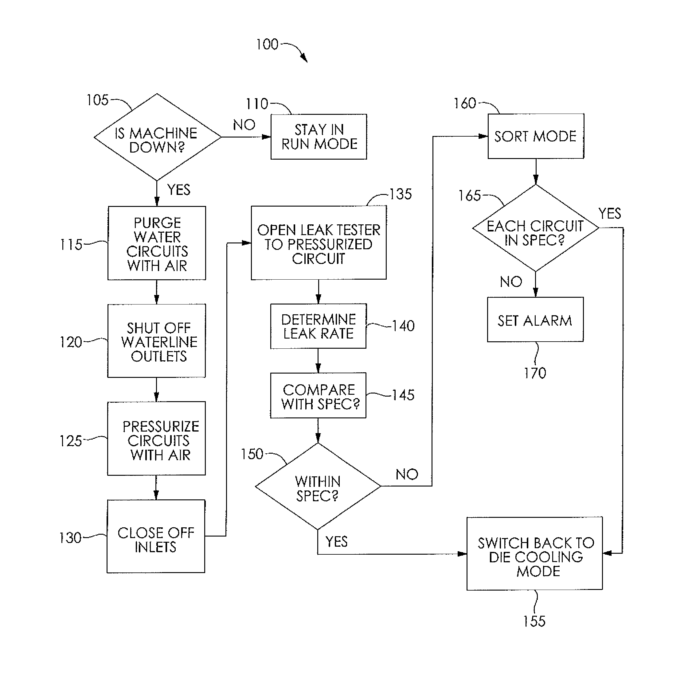
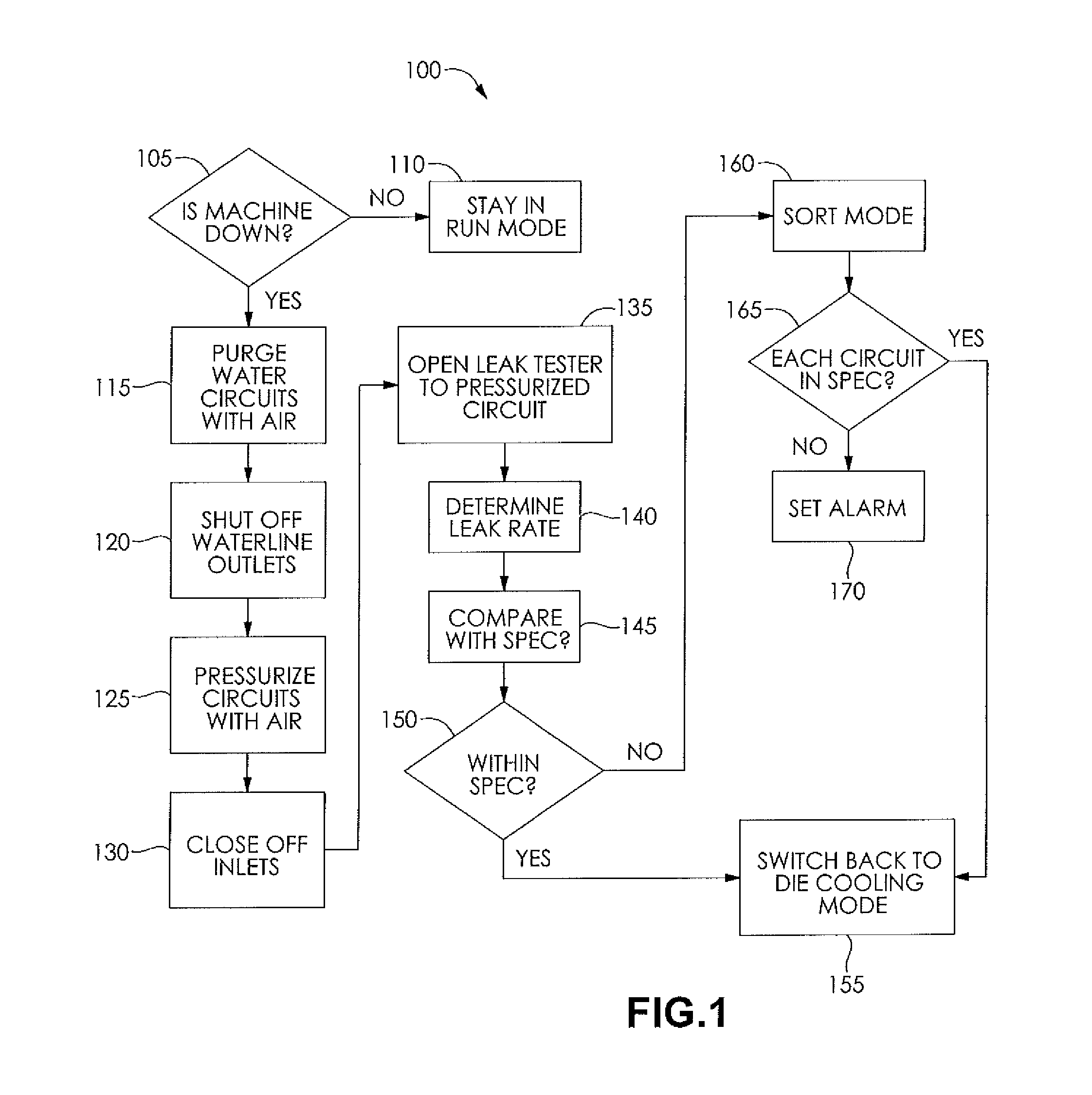
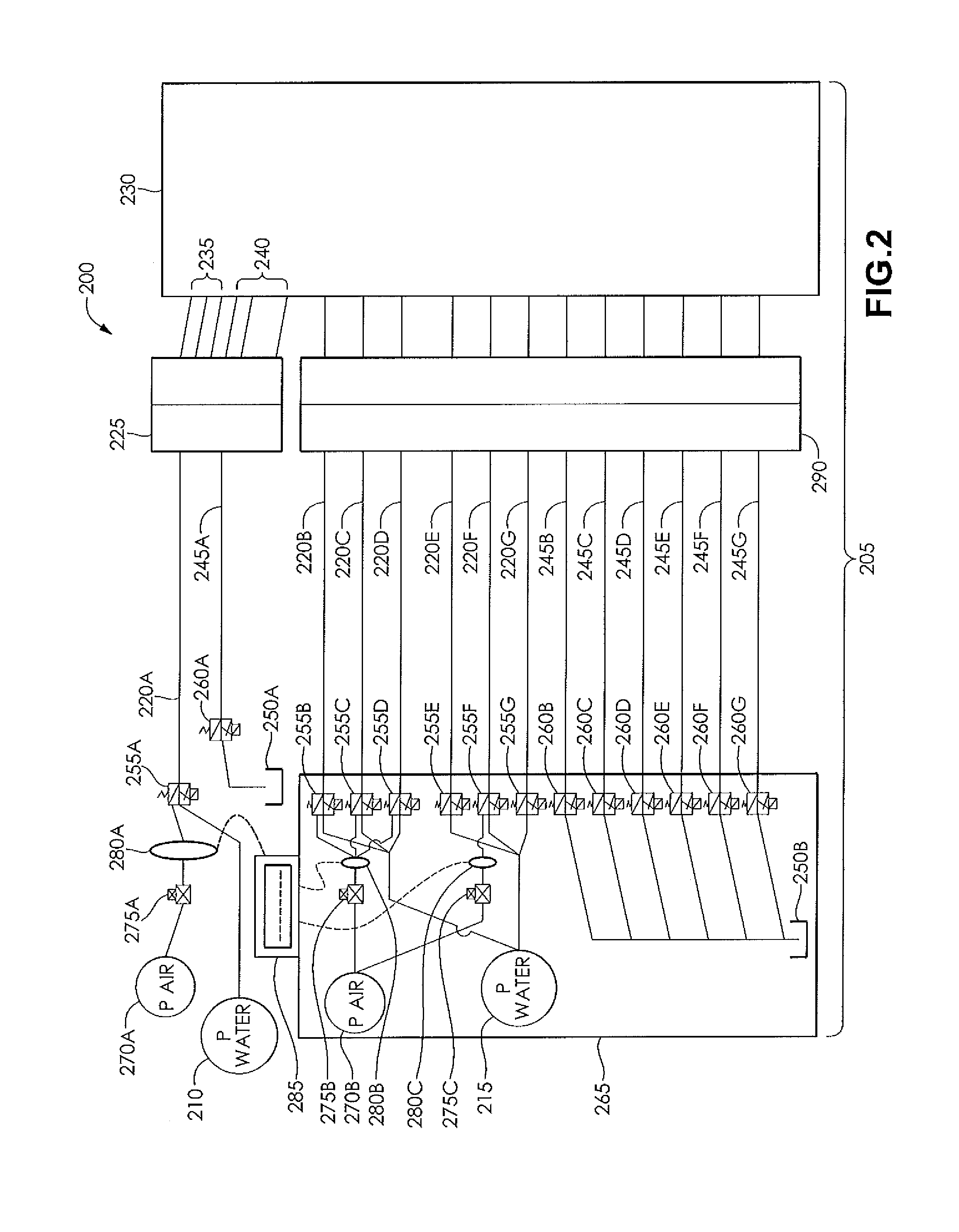
[0015]The present technology provides die cooling systems with integral and automatic leak testing. One or more valves, leak sensors, air decay units, and added machine controls are included in a die cooling system to enable on-board leak testing of a die while installed in a die casting machine. The die cooling system includes air purge and controlled shut off valves to test for leaks using pressurized air. An air decay sensor is in communication with o...


PUM

PropertyMeasurementUnit
pressureaaaaaaaaaa
gas pressureaaaaaaaaaa
pressure decayaaaaaaaaaa

Abstract

Systems and methods allow detection and location of die coolant leaks while a die is in a die cast machine and at operating temperature. The testing can be performed during normal down time of the die casting assembly and repeated as desired. Cooling circuits of the die can be tested in zones where zones are sorted to identify particular cooling circuits as having leaks as necessary. Valving, leak sensors, air decay units, and added machine control are provided in the die cooling system to enable onboard leak testing of the die while installed in the die casting machine.

Description

FIELD OF THE INVENTION[0001]The present technology relates to detection of coolant leaks in die casting, including detecting and pinpointing die coolant leaks while a die is in a die cast machine.BACKGROUND OF THE INVENTION[0002]This section provides background information related to the present disclosure which is not necessarily prior art.[0003]Various casting processes for forming articles can use dies having a mold cavity with cavity inserts that can include one or more core elements. The mold cavity can be formed of outer molds and inner core elements each having features and reliefs that form details, recesses, and cavities in a casting when molten material such as liquid metal is poured or forced into the mold. For example, casting processes can be used to form engine blocks and transmission housings from molten aluminum alloys for use in internal combustion engines and transmissions for vehicles and other applications. Inner core elements can be constructed from bonded sand ...

Claims


Application Information

Patent Timeline
11 Jul 2013
Publication
US20130174648A1
IPC
G01M3/04; B22D11/22; B22D17/08
CPC
B22D17/2218
Inventors
WARD, GARY C.